

This series of articles talks about power supply topics and the challenges power rails can pose for noise-sensitive RF and signal chain applications. A simple question is asked in these articles: A noisy power supply can ruin your signals; how do you keep power rails “clean”?
For many years, electronics engineers have discussed "signal integrity" but now there is increased awareness of how “power integrity” affects RF and signal quality. It’s a fair observation that the power integrity discussion started in the late 20th century around how to properly power a microprocessor demanding high level current transients from its power rails. This was experienced in the eco-systems of Intel and Sun Microsystems, used inside personal and business computers. For example, Dr. Istvan Novak presented at DesignCon in 2000 about impedance measurement of PDN, "Measuring MilliOhms and PicoHenrys in Power Distribution Networks." Now, various kinds of microprocessors have been introduced into the market, such as DSPs, FPGAs and GPUs, and the subject of how to handle current transients is recognized as an increasing PDN (Power Distribution Network) challenge.
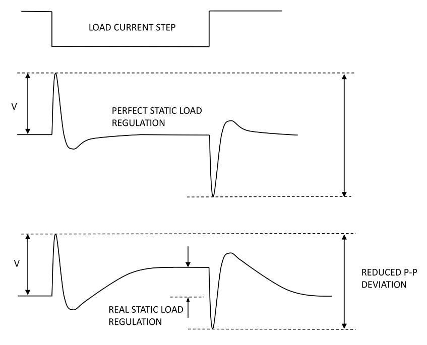
Initially, PDN design was more related to power supplies for digital systems, to ensure and maintain accurate logic high and low levels. For example, too much power rail undershoot caused by a load current transient could flip logic states, or too much overshoot could damage the processor chip. With a small margin between allowable under- and overshoot peaks, along with ever-lower rail voltages, special techniques have been developed such as described in the Intel Mobile Voltage Positioning (IMVP) specification, where introduction of deliberate “droop” with load transients limits total voltage excursion (Figure 1).
The increased current demands of systems can be categorized as follows, in order of time getting a target of PDN design:
- Computers: More integration of transistors in CPUs demands higher current and better handling of load transients
- Embedded Processing: DSPs, FPGAs and/or GPUs are handling higher data throughput and demand higher current with higher load transient levels
- High speed Communication: The ballooning of digital data demands higher current in communication interfaces
These increased demands are the major driving force in the bid to improve power integrity. This is because of the simplest and most important rule: Ohm’s law. In PDN considerations, Ohm’s law translates as a target impedance ZTarget as shown in Equation 1 from an article by Larry Smith, Steve Sandler and Eric Bogatin (1). The equation establishes the highest impedance a processor die should see looking back into the PDN. If the PDN impedance stays below this limit, even the worst-case transient current into the die will generate an acceptably low rail voltage transient.
Z Target = ΔV(max-noise) /ITransient Equation 1
When we talk about power integrity, most of the time our "power rail" is a voltage regulator, sometimes called a Voltage Regulator Module (VRM). Heidi Barnes at Keysight Technologies summarized this nicely in her article, "A POL power supply is typically a switched mode power supply with a buck regulator DC/DC converter design. The microprocessor printed circuit board world call this a voltage regulator module. All these terms are interchangeable and refer to the source of power" (2).
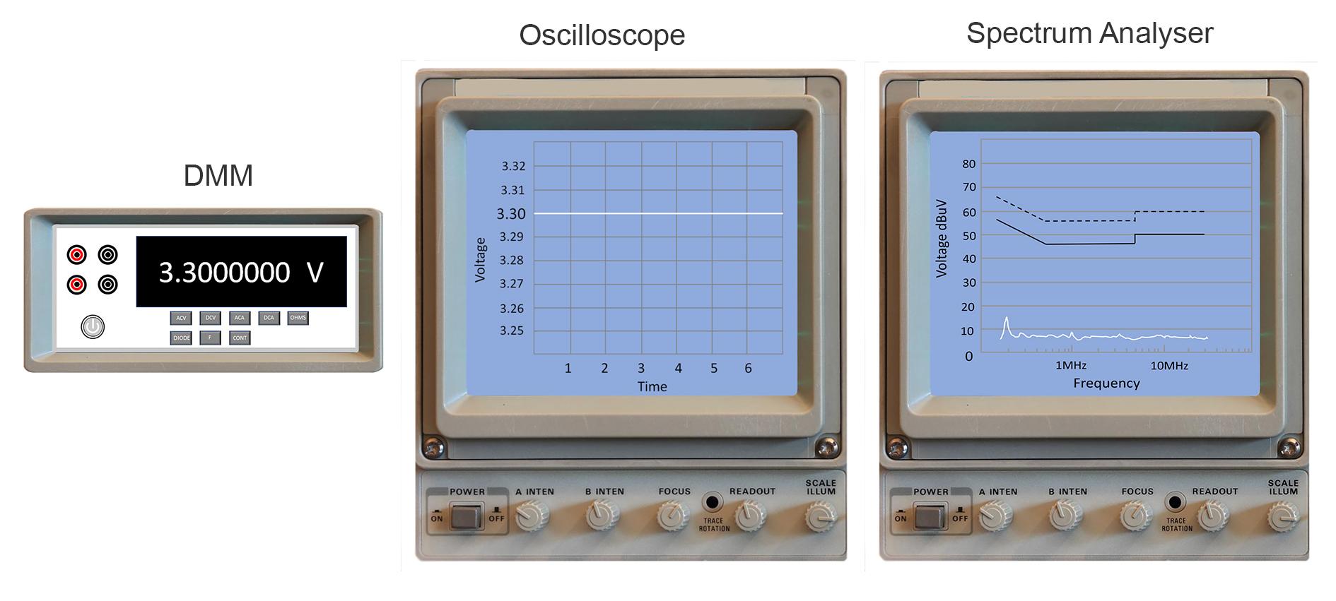
A VRM is supposed to output a rock solid, flat-line voltage over time to its load devices, no matter how high the load current or how fast load current transient events occur. Any deviation from the VRM’s target output voltage is treated as an error or noise. Here, we use the phrase "error voltage" more in its DC meaning. In contrast, the phrase "noise voltage" is more in the AC or frequency domain meaning. So, our perfect and ideal DC power supply, for example with a 3.3V target, shows the following characteristics:
- 3.300000000… Voltage reading with a well-calibrated, accurate DMM (digital multi meter)
- A flat line on an oscilloscope using the most sensitive voltage scale
- No visible signal power when monitoring the 3.3V output with a frequency spectrum analyzer, down to its noise floor
- DC output voltage errors
- A reference voltage within the VRM is off the target
- An error amplifier in the VRM has an offset voltage on its positive "+" or negative "-" input ports
- Dynamic/AC output voltage errors
- The VRM feedback loop has AC noise sources - all resistors, transistors and diodes in the VRM system add noise in its regulation action
- Finite load regulation of the VRM
- The VRM has a load current dependency.
- Finite output Impedance of the VRM
- The VRM has a dynamic/AC load current dependency in the frequency domain. See equation 1
- Finite line regulation of the VRM
- The VRM has an input voltage dependency
- PSRR, Power Supply Ripple Rejection
- The VRM has a dynamic/AC input voltage dependency in the frequency domain
An important factor to note for this entire series of articles is that the VRM output voltage is normally distributed to multiple load devices and cannot be fully accurate at every one.
This is no different from RF or signal chain circuit designs.
Check out https://p.qorvo.com/qspice.html to sign up for an early copy of QSPICE - a newly written and upgraded SPICE based simulation package.
References
1. “Target Impedance is not enough”, Larry Smith, Steve Sandler, Eric Bogatin, Signal Integrity Journal, Jan 16 2019.
2. “High-Speed Digital Design Success Demands A Modern Workflow”, Keysight technologies’ white paper.