Figure 1 TerreStar GENUS™ Smartphone.
Antenna performance evaluation is a key step to understanding the performance behavior of an antenna design. Planar inverted-F antennas (PIFA) are often applied in terrestrial cellular phones. At EB, the first GMR-1 3G satellite-terrestrial smartphone was designed, using an internal PIFA antenna configuration for the satellite mode. The handset also integrates the radio technologies of GSM/WCDMA, GPS and WLAN/Bluetooth. The satellite RF front-end is designed for open and remote areas in the case where no cellular network is available. Figure 1 shows the picture of the handset, which has a similar size and weight as a standard cellular smartphone. In antenna design for a specific communication system, a number of prototypes must be built and their antenna gain performance measured in an anechoic chamber. To select the best antenna prototype for the system, the performances of the prototypes should be evaluated by passing a multipath fading channel, which is typically characterized by slow or fast Rician fading channels in GMR-1 3G standards.1 A Rician channel is independent on the transmit and receive antennas. Here, the Rician slow fading channel weighted by the patterns is applied to evaluate the performance of the prototypes and to estimate the fade margin for the system design. The preferred elevation angles are from 20° to 50° and the interested frequency is at S-band.
Antenna Measurements
The PIFA is located at the upper right corner of the handset from the front view. Several prototypes were built and measured in an anechoic chamber with approximately 3° angular steps in both the azimuth and elevation planes. The phone and hand positions are shown in Figure 2, where the phone is tilted by an angle θ = 60° from the zenith direction to the centre axis of the handset in the head-hand measurements. Three hand positions (HP1, HP2 and HP3) are selected for both the right and left one. They are defined respectively by 3, 5 and 7 cm distances from the thumb to the upper edge of the phone.

Figure 2 Phone and hand position in the antenna measurements: (a) phone position and (b) HP1, HP2 and HP3 hand positions.

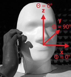
Figure 3 Measurement coordinate system.
Figure 3 shows the coordinate system for the phantom head with hand measurements. The handset beside the right and left ear, using both the right and left hand, was measured. For free space (FS) measurement coordinates, the head shown is replaced by the handset with the keyboard towards the Z axis. Many different setups were also measured, such as data mode and other real user cases. In this article, the free space and the handsets beside the right ear with right hand are investigated without loss of generality.

Figure 4 The FL and RL PIFA pattern for FS.
Internal PIFA Patterns
The PIFA patterns were measured on both the forward link (FL) and return link (RL). The FL is defined as the signals from the satellite to the handset; the RL is defined as vice versa. LHCP (left-hand circular polarization) and linear polarization are applied in the FL and RL, respectively. For all the setups, the three dimensional patterns are plotted by using the measured PIFA gains with approximately 3° angular resolution in both the azimuth and elevation plane. Figure 4 shows the patterns for the FL and RL of the three prototypes under test. It is seen that the patterns of the three prototypes are very close. The RL patterns are better than the FL patterns due to the gains contributed by the total transmitted power. The FL patterns are also very good in the required elevation angles.

Figure 5 The FL patterns for the PIFA prototypes; handsets held in the right hand beside the right ear with HP1, HP2 and HP3.
Figure 5 shows the PIFA patterns for the FL with the phantom head and hand. It can be seen that the head as well as the hand have a large effect on the PIFA gain patterns. The phantom head has more of an effect compared with the different hand positions (HP1 ~ HP3). HP1 is the worst because the thumb and the hand are closer to the PIFA location. HP2 and HP3 look comparable. In the back cover of the handset, a warning line is plotted to remind the users to hold the handset correctly.

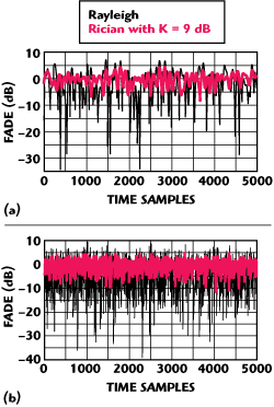
Figure 6 Rayleigh and Rician (k = 9 dB) fading channels for a moving terminal with a Doppler shift: (a) 10 Hz and (b) 100 Hz.
Multipath Fading Channel
Multipath propagation is the key characteristic in mobile communications and causes channel fading. The typical multipath fading channels are Rician and Rayleigh channels. In GMR-1 3G,1 slow and fast fading Rician channels are recommended to be applied in the system and link level simulations. The slow fading channel is defined with a Doppler shift of 10 Hz and 9 dB Rician factor, while the fast fading channel is with a 100 Hz Doppler shift and 12 dB Rician factor. Figure 6 shows the slow and fast fading Rician and Rayleigh channels, where the Doppler shift and sampling time are 10 Hz and 0.001 s, respectively, and the Rician factor 9 dB is taken for Rician channel simulations. It is seen that the Rayleigh channels have a deeper fast fading and Rician channels are much better. When the mobile terminal is moving fast, 100 Hz Doppler shift, the channel fading rate will increase, which makes the channel worse. In this work the slow Rician channel will be used in simulations and the fast fading channel can be done in a similar way.
Antenna Performance Evaluations
Assuming that GT(θ, φ) and GR(θ, φ) are the antenna patterns for the transceiver, respectively, and H denoting the fading channel gain by multipath, the received power can be calculated by
Pr=GT(θ, φ)·H·GR(θ, φ) (1)
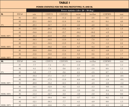
For antenna performance and fade margin estimation purposes, the handset can be taken either as a transmitter or receiver and the satellite gain pattern is assumed to be unknown. The received power statistics can be tabulated using the values of the minimum, CDF 1 percent (CDF: Cumulative Distribution Function), CDF 10 percent, mean, median, CDF 90 percent and the maximum. From the power statistics of the prototypes, the best prototype can be selected for mass production. Moreover, the fade margins required in both the forward and return links can be seen and further checked to see if they meet the system requirements.

Figure 7 Receive/ transmit power distributions: (a) FL and (b) RL.
Figure 7 shows the receive/transmit power distributions in the FL and RL for PIFA#1, from which the fade margins can be found by using the slow Rician channel weighted by the patterns. Moreover, it is seen how much the antenna patterns in free space as well as the head-hand setups can affect the power distributions, and how much deviations for the fade margin compared with the only Rician channel. In the figure, the fading caused by only the Rician and only the Rayleigh channels are plotted for the sake of comparison. It is seen that the antenna patterns have a big effect on the power distributions. Therefore, the measured power cannot be used directly to obtain the corresponding fading channel before removing the effect of antenna patterns. Table 1 shows the specific power statistics at different CDF points for the prototypes. The elevation angles are from 20° to 50° as the system required. In the phantom head with hand setups, the measurements of the handset beside the right ear (BHR) are analyzed. It is seen in the Table that the FS setup has the best performance. For the phantom with hand setups, HP1 has worst performance. HP2 and HP3 results are almost identical in the FL, but HP3 is found better in the RL. Overall, the RL performance is better than FL. From the Table, it can be seen that:

- At CDF1 percent, the HP1 power statistics are worse than HP2 and HP3 by approximately 2 dB in the FL. In the RL, HP3 is approximately 2.5 dB better than HP2 and HP2 is approximately 5 dB better than HP1.
- Compared to the FS, the head-hand setups are approximately 4 dB lower in the FL. In the RL HP1 case, the power is approximately 10 dB lower at CDF1%.
- The RL is with less fade margin.
- By different system reliability requirements, the fade margins are available.
Conclusion
The internal PIFA prototypes for a satellite-terrestrial handset are evaluated by multipath Rician channels. Moreover, the fade margins are provided for the FL and RL by the system reliability requirements. The head and hand have a large effect on the antenna gain patterns and further affect the final power statistics. One cannot tell what the exact channel is without taking out the effect of the antenna pattern(s).
Acknowledgments
The author would like to thank his colleagues from EB, Terrestar Networks (TSN) and RKF Engineering for aiding in this work, especially Jari Inget, Petri Myllylä, Tuomo Haarakangas, Jyrki Alasalmi, Juha Katajisto and Mikko Niemi at EB, Joe Martinet at TSN, and Jeffrey Freedman and Ted Kaplan at RKF. Special thanks go to Ari Immonen and Mari Kähkönen at EB for sponsoring and support in drafting the paper. Thanks to Arto Nurro for helping to improve the quality of the pictures. The views expressed herein are the authorís and may not reflect the views of EB, TSN or RKF.
Reference
- "Radio Transmission and Reception," GMR-1 3G 45.005, ETSI TS 101 376-5-5, v3.1.1 (2009-07).
