Figure 1 Families of equal power dividers.
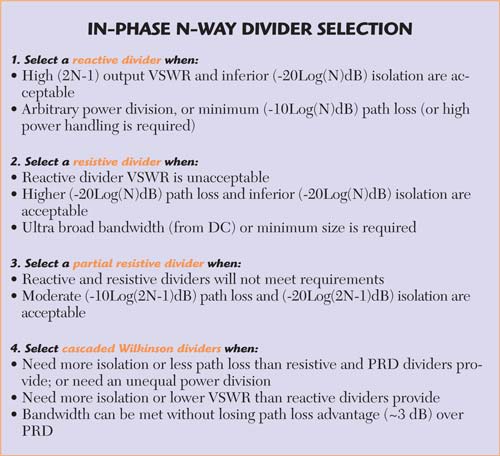
The "partial resistive divider" (PRD) is often overlooked when selecting a power divider circuit. This article compares its attributes with those of resistive, reactive and Wilkinson divider circuits. Figure 1 shows the basic resistive, reactive, partial resistive divider (PRD) and Wilkinson divider circuits. There are 1 through N equal output branches.
Pros and Cons of the Approaches
Resistive dividers offer minimum size and a perfect match without transformers. The tradeoffs are a path loss twice the split loss, isolation only twice the split loss, a low (1 to 100 mw) input power limit, and only an equal power split.
The PRD match is limited only by the input transformer, which has an impedance ratio of approximately half the number of outputs. The path loss is less than 3 dB more than the split loss. Isolation is twice the path loss and up to 6 dB better than the resistive and reactive divider isolation. The input power handling is more than twice that of the resistive divider, but less than the reactive and Wilkinson circuits. As with the resistive divider, it is limited to equal power divisions.
The reactive divider input power is limited only by the transmission lines; the output power split can be unequal. Its input match is limited only by the input transformer, but that has an impedance transformation twice that of the PRD. Its output VSWR is almost twice the number of outputs. Also, a failure at one of the output loads can short out all the outputs.
The Wilkinson input match has the same impedance transformation as the reactive divider. The input power can be large, but will be limited if the output loads are not perfect. The output powers can be unequal. The output match and isolation can be very good. Wide bandwidth with multiple outputs or unequal output powers is very difficult in an individual unit. Cascading units to obtain multiple outputs adds to path losses and match problems.


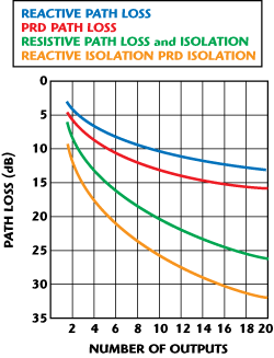
Figure 2 Path loss and isolation values for different power dividers.
Resistive, PRD and Reactive Divider Design and Performance
The values in Table 1 assume perfect transformers and resistors. The input and output impedances are assumed to be equal (Zo). The values obtained from Table 1 can be used to design a PRD for any number of outputs. Figure 2 shows the path losses and isolation for the three different power dividers. A narrow band and a wide band application are described below.
Narrow Band 22-Way L-Band PRD
This unit was prototyped for possible use in Iridium communications satellites. The path loss (27 dB) of a resistive divider would be excessive. The high output VSWR (43:1) of a reactive divider ruled it out. (Adding circulators to a reactive divider would add complexity and weight.) A cascaded Wilkinson divider would be much more complex. A single-stage, 22-way Wilkinson divider would not be practical. Cascaded unequal power split Wilkinson dividers would be complex, large and lossy.

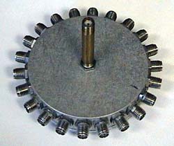
Figure 3 Photograph of a 22-way PRD.
The PRD unit is pictured in Figure 3. This unit uses an axial quarter wavelength coaxial input transformer. The prototype body size was determined by the minimum clearances required between the SMA output connectors. In the final system configuration, with direct soldered output pins, the diameter would be much smaller. The as-built test results are summarized in Table 2. Note the broadband isolation and output VSWR. Although it met expectations, the unit was not used in production because the customer changed the requirement to an unequal output power split. This is one of the limitations of the simple PRD approach. All output powers are equal and in-phase.

BroadBand (475 to 8050 MHz) 8-Way PRD
This unit is an 8-way partial resistor divider, which covers the frequency range from 475 to 8050 MHz. Resistor dividers were a real possibility, but would have had an unacceptably high (approximately 20 dB, including circuit loss) path loss.
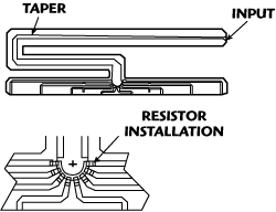
A reactive divider would have a longer transformer and high output VSWR (15:1). Three stages of cascaded 2-way Wilkinson dividers would be larger with high path loss. This unit shows both the PRD design capability and some of its shortcomings. The input transformer is a 3/8 wavelength at 475 MHz Klopfenstein microstrip tapered line. The taper includes two mitered 90 degree bends. A copper alloy block on top of the microstrip at the split point spreads the resistor heat over a larger area.

Figure 4 Eight-way PRD.
Although unrelated to the divider design, the blind mate OSP connector design may be of interest. The "shells" are machined into the body, thus eliminating another build up of true position error, which separate shells would introduce. Figure 4 shows the resistorís installation in the 8-way PRD.
The unit performance shows the effect of finite element size and circuit losses. The insertion loss increases up to 2.2 dB with frequency. The longer path length to end ports introduces up to 1.6 dB output amplitude unbalance at high frequencies. The isolation rolls off to 18 to 19 dB at 8050 MHz (compared to 23 dB theoretical isolation with ideal elements). The production specifications are shown in Table 3.

Conclusion
The design of partial resistor dividers is straightforward using available equations. They can use either lumped element or distributed element input transformers. Measured results show that the partial resistor divider is a useful in-phase, equal power split, design approach.
Harry F. Chapell received his BS degree in Physics from Worcester Polytechnic Institute in 1954. From 1954 to 1955 he was a member of the technical staff at Bell Telephone Laboratories. He developed high power crossed field oscillators and amplifiers at Raytheon Power Division from 1955 to 1963. He advanced to Vice President of Research and Development at Sage Laboratories while developing passive microwave devices over the period from 1963 until his retirement in 1996.

