
Magnetic resonance imaging (MRI) scans may cause harmful tissue heating in patients with active and passive implants,1 such as pacemakers, deep brain stimulators, stents and prosthetic implants, as a result of the applied RF magnetic field (B1) of 64 MHz at 1.5T and 128 MHz at 3T. Consequently, patients with implants are preventively excluded from receiving diagnostically valuable MRI scans.
Mechanism of RF Heating in MR
The two primary mechanisms for coupling the RF energy to the implant are 1) the B1 orthogonal to the implants forms a conductive loop and 2) the induced E-field components in the tissues are tangential to the implant path (without implant present) as a result of the B1 exposure of the patient. The collected RF power over the entire length of the implant may be deposited very locally, e.g. at the tip of implants. The heating depends on the following parameters:
- B1 rms
- body coil design
- position and posture of the patient in the MR scanner
- outer and inner anatomy of the patient
- implant trajectory
- implant length
- RF properties of the implant
- implant geometry at the location of maximum energy deposition
- 3-D distribution of the energy deposition
- thermal properties (heat capacity, conduction, perfusion, etc.) at the location of energy deposition
This list illustrates the complexity of analyzing worst-case heating even in a defined patient group independent of the scanner.
Objectives
Patients with active and passive implants will only be able to benefit from MRI diagnostics if the devices are inherently safe under worst-case conditions. This paper describes the possible methods and the available tools to demonstrate with known uncertainty that the induced heating under worst-case conditions is below the threshold of harmful thermal effects.
Anatomical Human Models
Since the exposure of the implant is a strong function of the anatomical features, the evaluation must include the anatomies of the entire patient population with respect to age, body mass index (BMI) and height.2 Small postural changes may also influence the exposure significantly (e.g. loops formed by arms and legs); therefore, manual manipulation may be necessary to accommodate these changes. If the entire implant inside the model requires evaluation, anatomically correct placement of the implant is also necessary.

Figure 1 The Virtual Family: Duke, Ella, Billie and Thelonius.

Figure 2 The Virtual Classroom: Louis, Dizzy, Eartha and Roberta.

Figure 3 The obese male phantom.
The most advanced and suitable models for such investigations are The Virtual Family,3,4 which was jointly developed by the IT'IS Foundation and the US Food and Drug Administration (FDA). It consists of four full anatomical 3-D surface models of an adult female, an adult male, an 11 year-old girl and a six year-old boy (see Figure 1). The models were developed from high-resolution MR imaging data of four volunteers. All models were reconstructed from several hundred MR-images as three-dimensional surface meshes, thus overcoming the drawbacks of conventional voxel representation. This allows free positioning and rotation of the models in the computational domain. The models contain up to 84 different types of tissues and organs, and can be meshed at arbitrary resolutions without the loss of small features. The Virtual Family is now complemented by The Virtual Classroom (see Figure 2). Another suitable model is the obese adult man (see Figure 3) from Schmid & Partner Engineering AG (SPEAG)5 that was developed using the same techniques. All models can be fully customized for resolution and posture using SEMCAD X.6
EM Modeling
Numerical modeling techniques such as the conformal finite-difference time domain7,8 solver from SEMCAD X are commonly used when inhomogeneous, anatomical models require simulations of RF exposure. MRI safety investigations of implants may include detailed RF models of the implants, the complex anatomical models and the RF exposure system. Therefore, sub-millimeter resolution in a several cubic meter domain filled with hundreds of biological sub-domains must be numerically and efficiently solved. This can only be obtained within a reasonable time with innovative simulation techniques.
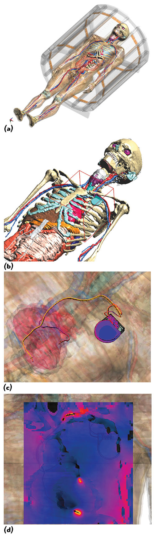
Figure 4 Duke (from the Virtual Family) with implanted pacemaker/leads, located inside a 64 MHz RF birdcage (a); Huygens Box (red) around pacemaker (b); induced surface current distribution (c); SAR distribution (d).
Figure 4 shows an example of a simulation of a pacemaker implant placed within an anatomical adult model from the Virtual Family inside a 64 MHz RF MRI birdcage coil. The overall simulation of the original 120 million cells can be performed within a few hours and with grid resolutions of much less than one millimeter using a two-step approach (Generalized Huygens Box Method).7,9 A first simulation of the birdcage without the pacemaker lead is performed using a relatively coarse grid (15 to 20 million cells, graded mesh). The fields are recorded on the surface of a rectangular box, placed at a distance of a few centimeters around the lead wire and the mounting device, and are used to excite a second simulation with the lead present. This second simulation is restricted to the vicinity of the lead and has a graded mesh with maximum refinement at the implant.
Temperature Modeling
Electromagnetically induced effects in the lead are directly coupled to temperature elevation within the surrounding tissues. For implant safety investigations it is necessary not only to accurately calculate temperature distribution and heating effects at the implant-tissue interface, but also in the surrounding tissue. Blood pooling and various perfusion effects must be evaluated over a large parameter space. Tools like the Thermal Solver from SEMCAD X can generate tensorial perfusion tissue models as well as discrete networks of 1D vessels.
Experimental Evaluations
In silico evaluations are key to demonstrating MRI safety, but must be anchored to the real world by additional experimental evaluations, e.g. 1) combined numerical and experimental evaluations and 2) a full numerical evaluation. In the first approach, only the incident field as well as the transformation between energy deposition and in vivo temperature rise are determined by numerical means, whereas the energy deposition is determined experimentally under worst-case incident field conditions. In the second approach, the implant is modeled for the various configurations in all models representing the patient population. Since this approach also requires modeling of the device under test (DUT), the model must be validated experimentally under known exposure conditions.

Figure 5 Picture of the medical implant test system (MITS 1.5/3.0 from ZMT Zurich MedTech); birdcage in horizontal operation, with ASTM phantom, probes and EASY4MRI measurement equipment (a); Birdcage in vertical operation with DASY5NEO near-field-dosimetry scanner (b).

Figure 6 (a), (c) The leads are fixed in the mounting device together with the guiding glass tubes and temperature measurement probes. Some gel is visible in (c); (b) and (d) show the liquid filled phantom in the birdcage coil with the DASY5NEO robot scanning an E-field probe. A lead can be recognized in (d) at the left side of the ASTM phantom.
Test suites such as the MITS 1.5 or the MITS 3.0 from ZMT Zurich MedTech10 provide a solution to perform experiments under very well-defined field conditions for RF heating and EMC exposure (see Figure 5). The magnitude and polarization are controlled independent of the load using isotopic H-field probes combined with EASY4MRI from SPEAG for MR applications. ASTM,11 elliptical or custom-made phantoms filled with high or low conductive media can be positioned inside a 16-rung RF birdcage coil that represents a worst-case approximation of the coils used in available 1.5T and 3T MRI machines. Figures 6a and c show an example of an evaluation in an ASTM phantom utilizing a polyoxymethylen (POM) support for positioning temperature probes.12
These test suites have the advantage that measurements can be conducted with the birdcage in vertical orientation (see Figures 6b and d). This permits the application of a dosimetric near-field scanner robot to perform measurements along a predefined path or within a defined volume around the implant during the RF field exposition. This configuration is the setting in which the modeling outcome and measurement results can be compared with highest accuracy and lowest achievable uncertainty. The setup can be used to perform E-field, H-field, specific absorption rate (SAR) and temperature measurements with a robot-scanned grid. ASTM phantoms for vertical use with only the small 'foot'-side open for access or the new oval phantom for implant testing from ZMT can be used in such a configuration. Scanned measurement phantoms should be filled with a liquid, since measurement probes do not have to be embedded at fixed locations. Liquids may follow the new IEC technical specification.13
Uncertainty Budget
There are various testing and modeling approaches to accommodate the diversity of implant configurations and specific applications are possible. In order to obtain reliable results and consistent evaluations independent of the approach, the uncertainty budget should be determined for a certainty coverage factor of the patient population. Methodologies for determining uncertainty experiments involving quantities that cannot be assessed by statistical means have been developed in the past, e.g. ISO/IEC "Guide to the Expression of Uncertainty in Measurement."14 It basically splits the total uncertainty into various uncertainty sources, which are independent or with limited interdependence, followed by the determination of the uncertainty from assumed statistical models.
Standardization
Due to the limitations of existing ASTM standards and methodologies for compliance testing, a new ISO/IEC standard13 on active implantable medical devices (AIMD) is currently being drafted to define the measurement and simulation techniques for demonstrating MRI safe implants. The standard will contain sections on exposure systems, measurement setups, probes, testing methodology, uncertainty assessment, and tissue simulating media and reporting.
Conclusion
The combined application of numerical modeling and experimental evaluation is the only methodology to demonstrate the MRI safety of implants. As significant progress has been achieved in recent years with respect to methodology and instrumentations, regulatory authorities will undoubtedly mandate minimal requirements based on this progress in the review process.
References
1. D. Formica and S. Silvestri, "Biological Effects of Exposure to Magnetic Resonance Imaging: An Overview," Biomed Eng Online, 3:11, 2004.
2. E. Cabot, A. Christ, S. Kuhn, M. Capstick, M. Oberle and N. Kuster, "Comparison of RF Fields Along Typical Lead Paths for Various Medical Implanted Devices in the Human Body and in Homogeneous Phantoms," Joint Meeting of the Bioelectromagnetics Society and the European BioElectromagnetics Association, Davos, June 2009.
3. A. Christ, W. Kainz, E.G. Hahn, K. Honegger, M. Zefferer, E. Neufeld, W. Rascher, R. Janka, W. Bautz, J. Chen, B. Kiefer, P. Schmitt, H.P. Hollenbach, M. Oberle, D. Szerba, A. Kam, J.W. Guag and N. Kuster, "The Virtual Family - Development of Anatomical CAD Models of Two Adults and Two Children for Dosimetric Simulations," Physics in Medicine and Biology, submitted.
4. http://www.itis.ethz.ch/index/index_humanmodels.html.
5. http://www.speag.com.
6. http://www.semcad.com.
7. A. Taflove and S.C. Hagness, Computational Electromagnetics: The Finite-Difference Time-domain Method, Artech House Inc., Norwood, MA, London, UK, Second Edition, 2000.
8. S. Benkler, "Robust Conformal Subcell Modeling for Electromagnetic Simulations in Time Domain," Series in Microelectronics, Vol. 184, Hartung Gorre Verlag, Konstanz, Germany, 2007.
9. SEMCAD X Team, "Effective EM Simulations with Micro-l Resolution in Macro-l Objects - Generalized Huygens Box Method," Microwave Engineering Europe, July/August 2008.
10. http://www.zurichmedtech.com.
11. ASTM, "F2182 02a: Standard Test Method for Measurement of Radio Frequency Induced Heating Near Passive Implants During Magnetic Resonance Imaging," ASTM International, 2002.
12. E. Neufeld, S. Kuhn, G. Szekely and N. Kuster, "Measurement, Simulation and Uncertainty Assessment of Implant Heating During MRI," Physics in Medicine and Biology, 54(13), pp. 4151-4169, 2009.
13. ISO/IEC, "ISO/IEC AIMD MR JWG Draft," 2009.
14. ISO/IEC, "ISO/IEC Guide 98-3:2008."
Michael Oberle received his Dipl. Ing. degree in Electrical Engineering at the Technical University of Karlsruhe, Germany, in 1993, and his PhD degree from the Swiss Federal Institute of Technology (ETH), Zurich, Switzerland, in 2002. He is currently Managing Director of ZMT Zurich Medtech AG, Head of the Medical Technology division at Schmid & Partner Engineering AG, and in charge of medical technology related contract research at IT'IS Foundation. He was co-founder and CEO of Miromico AG, a spin-off company from ETH Zurich, with focus on miniaturized medical devices and contract development and research.