Most modern microwave communication systems require balanced components as well as unbalanced structures. In some wireless applications, such as dipole antennas, balanced LNAs, mixers, power amplifiers and so on, a balun frequently connects a bandpass filter with balanced components.1,2 Recently, simple balun-BPFs and their design equations have been proposed and found useful to reduce the cost and size of the functional blocks in some microwave systems.1,3 However, a conventional Balun-BPF shows unequal skirt responses between the two balanced outputs because one output has two notches near the passband, but the other does not have any, which also limits the skirt steepness of the Balun-BPF characteristics.
In order to eliminate the restrictions of the conventional Balun-BPF, two substantially identical ring resonators are combined. The arrangement of the combining points of the two ring resonators is essential to obtain symmetrical output responses. An interdigital-type inverter structure and the cross-coupling effect between two ring resonators are also investigated.
Analysis of the Dual Ring Balun-BPF

Figure 1 Schematic of the proposed dual ring Balun-BPF.

Figure 2 Simulated frequency response for three different coupling positions.
Figure 1 shows the circuit schematic of the proposed dual ring Balun-BPF; Figure 2 shows the simulated frequency responses for the three possible dual ring structures that show the possibility of balun characteristics. The first ring can be coupled to the unbalanced port of a conventional Balun-BPF in three different positions (A, B, or C). Only the arrangement with position C shows the Balun-BPF characteristics with symmetrical notch responses at the balanced two output ports (port 2 and port 3). The other structures show Balun-BPF characteristics with asymmetric skirt response as the conventional one or a broken passband with asymmetric response.

Figure 3 Equivalent circuit of the proposed fual ring Balun-BPF.
The BPF equivalent circuit is shown in Figure 3. The admittance slope parameters (bi, bi') and inverter values (Jij) of the two ring resonators are as follows3

where Yin= Y032/Y0, and

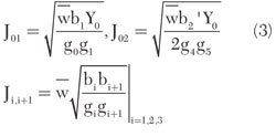
The Balun-BPF can now be designed with Equation 3, using the standard design method for a bandpass filter with J-inverters. Here, J02 was divided by √2 because there are two filter sections in a balun filter.3,4

As an example, the design specifications are chosen as f0 = 2.45 GHz, BW = 100 MHz and ripple = 0.03 dB. The calculated parameter values, using the above design procedure, are listed in Table 1.


Figure 4 Equivalent circuit for a λ/4 transmission line using an interdigital inverter.
The value of J23 is too small to be fabricated using a λ/4 microstrip line. Hence, an interdigital type inverter structure is proposed for the inverter, as shown in Figure 4, which has an additional advantage in size compared to a λ/4 transmission line inverter. The Y-matrix of inverters is well-known as


Figure 5 J and θc values for the coupling coefficient C and length ls of the interdigital inverter.
The value of the proposed inverter elements can be obtained by equating the Y-matrix of the proposed structure according to Equation 4 at the center frequency, using a commercial circuit simulator. Figure 5 shows the simulated J and θs values for each coupling coefficient, C, when Zeo = 169.6 Ω, physical length ls = 2, 3, 4 mm for θs and Zs = 111.062 Ω are used. The coupling coefficient is defined by Equation 5.5

The design parameters of the interdigital inverter for J23 = 0.0048 and ls = 3.00 mm are listed in Table 2.


Figure 6 (a) Schematic for circuit simulation of the proposed Balun-BPF; (b) approximation using six coupled lines for the dotted line parts.
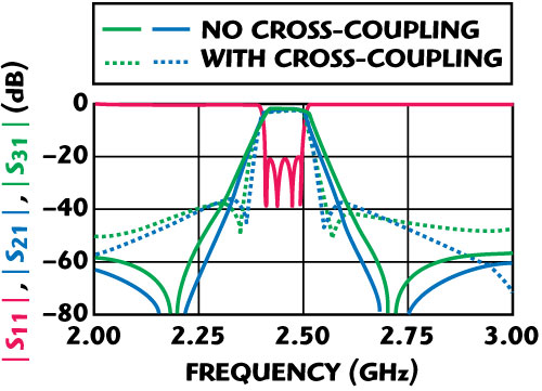
The cross-coupling effect from the proximity of the two ring resonators is also considered when the dual ring Balun-BPF is simulated. Figure 6 shows the schematic for the cross-coupling effect used with ADS™. The cross-coupling part of the two rings was approximated by dividing it into 6-coupled lines. Then each gap of the coupled lines Si is calculated with Equation 6, where Y1 = Y1', Y2 ≈ Y2' and R1 ≈ R1' are used and ui = 37.5°, 22.5°, 7.5°, and i = 1, 2, 3.

The result of the changes in the notch frequencies due to the cross-coupling effect is shown in Figure 7.

Figure 7 Frequency responses of the Balun-BPF with and without cross-coupling.
Simulation and Measurement Results
The simulations and measurements were performed using the commercial circuit simulator ADS, and vector network analyzer, Anritsu 37397C. The substrate used is WINUS IS640 with a thickness of 0.762 mm, a relative dielectric constant of 3.38 and a loss tangent of 0.0042.

Figure 8 Fabricated Balun-BPF.

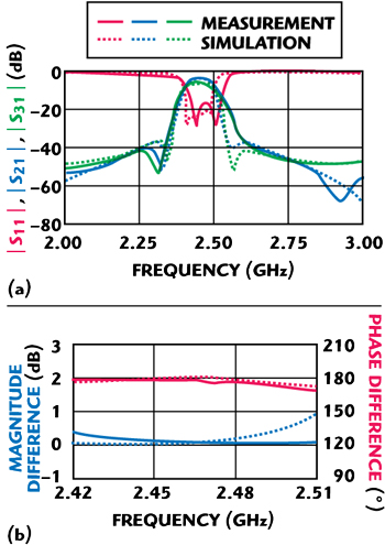
Figure 9 Simulated and measured results: (a) S-parameters and (b) magnitude and phase differences.
Figure 8 shows the fabricated dual ring Balun-BPF with two small tuning stubs. The 1 by 3 mm stubs, inside the rings, are used to finely adjust the slope parameters of the dual ring resonator. Figure 9 shows the simulated and measured frequency responses. The measured response shows the equal amplitude and balanced phase characteristics between the two balanced output ports as well as the symmetrical passband response and the intended sharp skirt responses of this excellent Balun-BPF.
Conclusion
The proposed dual ring arrangement shows excellent improvement in the symmetry and the skirt response of the two balanced outputs of a Balun-BPF. An interdigital type inverter structure for inter-ring coupling and the effect of cross-coupling between two rings are also discussed. The proposed concept of the dual ring Balun-BPF could be even more useful by applying the multilayer, LTCC or MMIC technologies for miniaturization.
References
1. E.Y. Jung and H.Y. Hwang, “A Balun-BPF Using a Dual Mode Ring Resonator,” IEEE Microwave and Wireless Components Letters, Vol. 17, No. 9, September 2007, pp. 652-654.
2. D.R. Huang and H.R. Chuang, “A 40 to 900 MHz CMOS Broadband Differential LNA for a DTV RF Tuner,” Microwave Journal, Vol. 50, No. 2, February 2007, pp. 128-136.
3. S.J. Kang, U.H. Park, H.Y. Hwang, “An Analysis of Three Port Ring Resonator for the Balun-BPF Characteristics,” Journal of the Korean Electromagnetic Engineering Society, Vol. 19, No. 4, April 2008, pp. 436-441.
4. G.L. Matthaei, L. Young and E.M.T. Jones, Microwave Filters, Impedance Matching Networks and Coupling Structures, Artech House Inc., Norwood, MA, 1980.
5. D.M. Pozar, Microwave Engineering, Second Edition, John Wiley & Sons Inc., Hoboken, NJ, 1998.
 Seong-Jun Kang received his BS degree in Electrical and Electronic Engineering from Kangwon National University in 2007. His research interests include microwave passive components, microwave antennas and RF systems.
 Hee-Yong Hwang received his BS degree in Electronic Engineering from Seoul National University in 1988 and 1992, respectively, and his MS and PhD degrees in Electronic Engineering from Sogang University in 1995 and 1999, respectively.
