 Modern mobile satellite communication systems provide bidirectional broadband network access for moving ground, maritime and airborne terminals. Applications enabled by mobile SatCom systems include broadband Internet access, video conferencing and data transmission. Currently such systems—commonly called SatCom on-the-move—are being introduced on a large scale all over the world for commercial as well as for governmental (civilian and military) use. For mobile SatCom equipment the commercial Ku-band is often chosen since this frequency range offers a trade-off between reduction of antenna size on the one hand, and reasonable resistance to adverse weather conditions on the other.
A moving satellite terminal requires a highly sophisticated beam steering system in order to continuously track the satellite during operation. There are two basic technologies that can be employed for pointing an antenna beam: The electronically phased-array antenna and the mechanically steered pencil beam antenna.
When the latter system is used, the strong space restrictions imposed by a mobile SatCom terminal require the adoption of a small aperture antenna together with a low-profile pedestal. Likewise the rotary joints employed for signal transmission along the mechanical steering axes need to be small and often shaped specifically for the application.
Therefore, in order to provide equipment manufacturers with rotary joints tailored to the specific requirements of fixed and mobile SatCom systems, Spinner has developed two new rotary joint product families—single channel waveguide rotary joints for Ku-band, and dual channel coaxial rotary joints, which are suitable for Ku-band and intermediate frequency applications.
Both product lines follow a common design philosophy that is characterized by well-thought-out modularity that allows a large variety of solutions with a minimum number of different piece parts and excellent electrical and mechanical performance, allied to a simple and highly reliable design.
Single Channel Rotary Joints

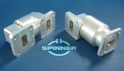
Figure 1 U- and L-shaped variants of the new Ku-band rotary joint family.
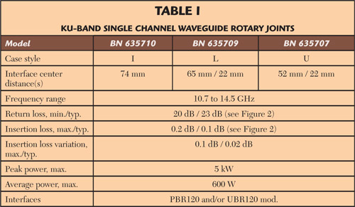
Figure 1 shows the U-shaped and L-shaped members of the product family, while the main characteristics of the Ku-band waveguide rotary joints are summarized in Table 1. Although realized in a non-contacting design, the Ku-band family is characterized by wide frequency coverage (relative bandwidth of 30 percent and above). An advanced electromagnetic design employing two stepped impedance transformers makes it possible to cover the full satellite band portion of the Ku-band with a high return loss and low insertion loss (see Figure 2).

Table 1

Figure 2 Typical frequency response of the new Ku-band rotary joint family.
These rotary joints are suitable for downlink frequencies (10.70 to 12.75 GHz) and uplink frequencies (13.75 to 14.50 GHz) as well as for the guard band in between. This last feature is being demanded by more and more customers. Figure 2 shows that any parasitic resonances are placed clearly outside the specified transmission band.
Another significant feature of the single channel rotary joints is that they are able to handle high average power levels safely. This feature is a result of the low insertion loss and the method of construction, with large cross-section metallic parts that allow for efficient axial heat removal towards both ends of the joint.
Besides good RF performance the Ku-band rotary joints are characterized by a dust-tight design that is protected against water jets (protection level to IP65) by the inclusion of a dynamic seal. In order to accommodate this seal the torque is increased and the housing slightly lengthened, but both are kept to a minimum.
Dual Channel Rotary Joints
The newly introduced dual channel rotary joints belong to a universal product family that covers different preferential frequency ranges, different case styles and flanges. The predecessor to this family is the multi-purpose rotary joint BN153118 that is shown on the left of Figure 3.

Figure 3 I- and L-shaped variants of the new dual channel rotary joint family.
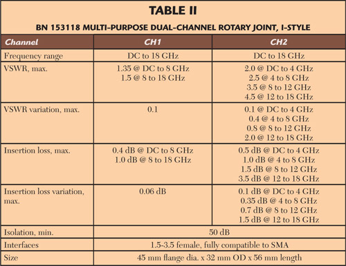
Its main characteristics are summarized in Table 2. This dual band rotary joint and its derivatives are realized with galvanic contacts at the center and outer conductors. As a result of this design each channel enables combined RF and DC transmission. This DC transmission makes it possible to supply active components on the rotating part of a platform (e.g. an LNA).

Table 2
Besides the I-shaped models like the one shown on the left in Figure 3, the new product family also includes rotary joints with L-shaped (shown on the right in Figure 3) and U-shaped housings that allow for a space-saving antenna pedestal design. These L-shaped and U-shaped variants significantly simplify the integration of the rotary joint. In order to cover a large variety of customer needs, the different basic case styles are available with standard and custom specific mounting flanges.
The different housing variants described above are just one advantage. Moreover, specialized versions are available that incorporate application specific tuning of the second channel in order to fulfill more stringent performance requirements within a dedicated frequency range. The L-shaped rotary joint BN 153146 shown on the right side of Figure 3 is an example of a variant optimized for SatCom use.
As a result of this optimization channel, CH2 of BN 153146 clearly outperforms channel CH2 of BN 153118 with respect to all RF parameters. At the expense of a narrower usable frequency range, channel CH2 of BN 153146 does now comply with a VSWR below 2.0 (compared to 3.5), a VSWR variation during rotation less than 0.5 (compared to 0.8), an insertion loss below 1.0 dB (compared to 1.5 dB) and a maximum insertion loss variation of 0.4 dB (compared to 0.8 dB).

Figure 4 Custom specific combination of a dual channel rotary joint with a slip ring assembly.
For applications that require a contacting transmission of supply power (DC, AC) or low frequency signals (analog, data), the dual channel rotary joints are also available in combination with standard and customer specific slip ring assemblies. Figure 4 shows a typical combination of an I-style rotary joint mounted within such an assembly.
Conclusion
These two new SatCom rotary joints that have been introduced by Spinner define a reference standard in electrical and mechanical performance. The Ku-band single channel waveguide rotary joints stand out due to their extremely wide transmission band. The dual channel rotary joint family features a unique variety of shapes in conjunction with its excellent RF data.
Spinner GmbH
Munich, Germany
+49 89 12601 1160
info@spinner.de
RS No. 301
