
In the beginning... (Around World War II), microwave circuits were heavy and bulky and consisted of voluminous, hollow metallic pipes and tubes known as waveguide. Microwave engineers working in waveguide were referred to as plumbers and their tools included files, ball-peen hammers, epoxy and paint. In the 1960s, planar transmission line circuits, based on two-dimensional layered topologies, were introduced. They were relatively cheap, lightweight and offered the potential for miniaturization, which quickly led to the concept of microwave integrated circuits (MIC).
MICs were also known as “hybrids” for their mix of active and passive components (some components are printed on a substrate, such as thin film caps or spiral inductors, while others are placed in chip form, typically active components such as diodes and discrete transistors). With an MIC, an entire circuit could be printed on one substrate with various components connected to each other in a continuous integrated fashion, thereby replacing individual microwave components connected by waveguide or coax cables. MICs could support mass-production and thus reduce costs. Circuit design, however, was still performed by hand using formulas from text books, pencils, Smith charts, a circuit board, some copper tape, a razor blade, soldering iron and test equipment. Either design task (MIC or waveguide) required a solid understanding of circuit behavior, astute observation of cut and try experiments… and a good deal of time.
Wright Pat and TI
In 1964, the Air Force’s Wright Paterson Aeronautical Lab requested Texas Instruments (TI) to submit a proposal for an airborne forward-looking radar system that maximized the use of semiconductors. The goal was to demonstrate that T/R modules could be manufactured at the price point commensurate with future large, active aperture phased-array and ECM systems.1 The resulting Microwave Electronic Radar Applications (MERA) program, which was co-sponsored by DARPA, would push the state of the microwave art and lead to the demonstration of microstrip transmission on semi-insulating silicon and gallium-arsenide substrates in 1965 including the first silicon MMIC, an X-band T/R switch in 1966, a 500 MHz tuned amplifier in 1966, the first gallium-arsenide MMIC, a 94 GHz local oscillator and balanced mixer in 1967.2 Out of the technical success of MERA, which culminated in the delivery of a complete operating radar system in 1970, other programs were started in most military radar houses throughout the US and abroad. Microwave circuit design would need to ramp up fast.
How did the TI engineers advance the state of microwave circuitry so quickly? One clue is found in US patent 3622762 filed in November 1971 by L.W. Dyer, T.W. Houston and G.J. Policky of Texas Instruments: “Using representations of circuit topologies and initial values of all elements, a circuit design may be modified by an automated data processing machine to improve operation for at least one performance characteristic by changing design variables. A desired circuit topology is selected and the initial values for all the circuit elements are coded and stored in the data processor. In addition, the desired performance characteristic is also selected and coded. Using coded input information, the data processor generates and stores a representation of a continuous analytical objective function. In the operation of the data processor, a value of the objective function is generated and stored.”
The patent abstract refers to a circuit simulation and optimization program developed internally by TI for microwave circuit designers supporting the MERA program. The program, known as CAIN (Computer Aided Integrated Networks), operated on an IBM 360 computer using punch cards as described by the patent filers in the August 1969 IEEE-Wescon technical paper, “Computer-aided Design of Microwave Integrated Circuits.”3 While TI engineers used this program for years, it was never commercialized by the company.
The First Commercial High Frequency Circuit Simulator
The benefits of using microstrip and stripline transmission lines, which included miniaturization and easier manufacturing, came at the price of design uncertainty. Among the issues, the inhomogeneous medium of microstrip results in an effective dielectric constant that increases with frequency so that the phase velocity decreases, the characteristic impedance changes and discontinuities such as bends, tees (line intersections) and line width steps need to be properly modeled to account for parasitics and accurately represent their high-frequency behavior. Before software, microwave engineers relied on text books and hand calculations in order to roughly approximate circuit behavior, a slow and tedious process.
While a few select companies had internally developed software on their mainframe computers, most microwave engineers at the time did not have access to computers or computer-aided design. Among them was Les Besser, who began his engineering career in 1966 in Hewlett Packard’s (HP) Microwave Division, developing broadband microwave components. It was at HP that Besser began working on simulators and impedance matching programs; although at the time, his manager disapproved of this side project.4
In the fall of 1969, Professor Ron Rohrer of UC Berkeley returned from a leave at Fairchild and taught a circuit design and analysis course. The course project was to develop the components of a comprehensive and optimal circuit simulator. The result was a program called “Computer Analysis of Nonlinear Circuits, Excluding Radiation (CANCER)”. The unusual name was chosen to reflect that the program was not funded by the defense industry, which provided funding for most circuit simulation programs at the time and required them to be able to test a circuit’s radiation resistance. One of the principle developers was grad student Laurence Nagel. Under the direction of his new advisor Prof. Donald Pederson (replacing Rohrer), Nagel developed the program into a public-domain general-purpose circuit simulator. The result was called SPICE (Simulation Program with Integrated Circuit Emphasis), which was released to the public as open-source code in 1972.5
However, SPICE could not address distributed transmission lines and was unacceptably slow for high frequency simulations. Without any commercially available ones, many companies (including Besser’s former employer, HP) developed in-house code. In 1970, Besser left to join Fairchild’s Microwave Division where he concentrated on MICs, GaAs FET amplifiers and CATV systems. At Fairchild, Besser wrote SPEEDY, a two-port analysis tool offering a transistor database with high-frequency device S-parameters for Fairchild transistors.
The program’s name was chosen to advertise the speed of the program in comparison to the existing time-domain simulators that were not well suited for microwave frequency analysis. At a time when computers (mainframes) were rare and prohibitively expensive, users could access this program worldwide via commercial timesharing through local telephone calls with terminals (i.e., teletype) and modems operating at speeds as low as 110 baud (bits/s).6 As slow as this was, design tools were faster than prototyping. In the case of ICs, SPICE was proving that they were absolutely essential.
Farinon Electric Co. hired Besser to direct their microcircuit design and development efforts. During that time he authored a program called COMPACT (Computerized Optimization of Microwave Passive and Active CircuiTs). In 1973, the same year that SPICE1 was first presented at conference,7 Besser commercialized his program and established Compact Software. This represented the first microwave CAD company and the first commercially successful microwave circuit optimization routine.
While limited in capability, it would set the path for future high-frequency design tools. The first versions of the software could only address ideal transmission lines and two-port elements that could be cascaded in series or parallel connections. Over time microstrip elements and discontinuity junctions were added. Later versions could do crude matching network synthesis and plot Smith charts using alphanumeric characters.6
According to Besser in his presentation on the history of MIC/MMIC inventions at IMS 2008 in Atlanta, “Recognizing that exact closed-form analytical solution for even a relatively simple microwave circuit, such as a single-stage feedback amplifier, was not practical, the first version of COMPACT included optimization of the circuit components. Although initially it was restricted to two-port type interconnections, generalized nodal connection and noise optimization were added in subsequent releases. (The) Circuit library included a wide range of components, as well as measured S-parameter databanks.”6
The ability to optimize complex microwave circuits eventually convinced many reluctant engineers to accept CAD as a practical design tool and as a result revolutionized circuit design. Time and again, the success of a software product would depend on its ability to improve engineering productivity and/or cut costs. Software with optimization capability offered to shave project times down from months to days, saving up to $24,000 per project according to the advertisements running at the time (see Figure 1).3

Figure 1 SuperCompact ad highlighting the per project savings using design software vs. hardware prototypes.
Initially, COMPACT operated only on big mainframes or commercial time — shared minicomputers costing engineering departments $3000 to $5000 per CPU hour (the personal computer did not yet exist). The user interface pre-dated schematic editors; therefore, circuits were defined by text via a netlist editor (see Figure 2). Remote terminals hooked up with 300 baud acoustical modems.

Figure 2 Example of a netlist with distributed transmission line models (TRL and OST).
In 1980, Compact Software was bought by Comsat and Besser remained associated with the company for the next three years before leaving to start a professional training organization called Besser Associates. During this time, a third-generation program known as SuperCompact™ was developed for mini-computers such as the Digital Equipment VAX, a design workstation, which cost about $250 K. The link between software and the operating platform played a major factor in the commercial fate of design software as the microprocessor and PC revolutionized electronic design throughout the 1980s.
A More Accessible Computer Platform
Entrepreneur Charles J. (“Chuck”) Abronson was co-founder of Amplica Inc. (1972) and served as CEO; he successfully managed the company’s IPO in 1981 and subsequent merger with Comsat in 1982. Amplica had used a design program called Magic to develop its state-of-the-art low noise amplifiers and achieve commercial success.
As a result, Abronson became a true believer in the power of design software. During the negotiation to sell Amplica to Comsat, he met Bill Childs, an employee of the Compact subsidiary. Together they teamed up to start EEsof in 1983.
EEsof focused on providing design software that targeted the inexpensive and rapidly growing personal computer, introducing their first product, the Touchstone® linear circuit simulator in 1984.8 While the initial netlist-based text entry was similar in format to SuperCompact, the move to the PC gave Touchstone a game-changing advantage and the company quickly ate into Compact’s market share.
EEsof furthered its product capability by adding links from its software to the HP8510 network analyzer. This allowed measured data to be captured directly into the analysis software. More importantly, the feature would entice those engineers dedicated to the “build and test” design method into using software. The so-called “Touchstone file” (also known as a SnP file after its set of file extensions) was originally the proprietary file format for the linear circuit simulator. The file format would become an industry standard for S-parameters (along with Y- and Z-parameters) used by circuit simulators and measurement equipment (VNAs) alike. This simple ASCII text file is now universally used to document the n-port network parameter data and noise data of linear active devices, passive filters, passive devices, or interconnect networks.
By 1985, the Compact Software subsidiary was practically bankrupt and Comsat essentially gave away the business unit’s product line assets to Communications Consulting Corp. (CCC)4 just as it had released SuperCompact PC version 3.09 to counter the growing popularity of Touchstone on the lower cost platform. CCC President, Dr. Ulrich Rohde, had deep roots in the industry, also being the Chairman of Synergy Microwave and Director with Rohde & Schwarz, the test equipment manufacturer. At the time, Rohde stated his intentions to “immediately increase the capabilities of Compact’s software products and to incorporate new microwave models.” The new company came with zero employees; however, Rohde immediately partnered with other technologists from around the globe and began focusing on model accuracy and new analyses.
Tool Functionality Grows as Vendors Compete
Combining circuit analysis software with test equipment data was well-suited to microwave product development in the mid-1980s. Touchstone and the HP8510 network analyzer were often paired together by engineering teams. Around this time, HP and EEsof were also tied together via a marketing relationship whereby HP sold and marketed Touchstone software on HP platforms such as the Series 200 (but not on the PC). The marketing agreement brought greater exposure for EEsof and help with entry into major defense contractors, further eroding Compact’s market share. It also provided entry into the design software market for HP and would set the stage for future competition.
The challenges of developing microwave components and even the network analyzer itself had convinced HP of the growing importance of design software. An internal tool, MANTIS (Microwave Analog Topology Interactive Simulator) was developed by Jeff Meyer who used it to help develop a broadband amplifier. HP executives concluded that design software would be a natural extension of the company’s strong position in the network analyzer market (and a capability the company would promote for many years to come).
Around this time, according to HP literature, “Hewlett-Packard engineers were developing advanced internally-used design tools, including its own highly-capable linear simulator that ran on the readily available workstations from the HP computer division.” In 1985, several key designers from the HP 8510 team were chosen to guide the development of software for the emerging microwave and RF design marketplace. The goal was “to integrate simulation, data display, and layout tools in a way that mirrored the way engineers really worked.”8
By 1987, the first version of the HP Microwave Design System (MDS A.01.00) was released. It had been developed in-house and comprised a linear circuit simulator with integrated schematic capture and graphical layout with back-annotation, a first for RF EDA software. MDS was offered on UNIX workstations from HP, Sun and Apollo as well on the PC (not Microsoft Windows but SCO UNIX). Schematic capture would help engineers enter their circuits graphically, thereby speeding-up design entry (for some) and providing a useful visual for circuit troubleshooting. To no surprise, the introduction of HP’s MDS product soon ended the marketing relationship with EEsof, at least temporarily.
Competition between Compact, EEsof and new-entrant HP sparked considerable innovation during these years. Also driving development was the DARPA program known as MIMIC. The overall goal of this program was to provide analog microwave and mm-wave sensors, based on gallium arsenide integrated circuit technology that would improve performance, size, weight, cost and reliability for the armed services (Army, Navy and Air Force). The program targeted CAE specifically as an area for development.
This program, similar to the earlier MERA program that fueled TI’s GaAs development, was announced in the fall of 1985 by Egbert Maynard, the czar of the DoD’s VHSIC program.7 In 1987’s MIMIC program “Phase 0”, each military branch awarded four teams between $750 K and $1 M to study the best way to develop and produce affordable, reliable, high performance MMICs. “Characterization of material and device processes and the development of computer-aided design capabilities” were specific program goals targeting design software.
The next year, the three services managed to agree on a single statement of work and selected the four teams that would move forward. In phase 1, EEsof would team with primes Hughes and GE and foundries AT&T, M/A-COM and Harris in a contract worth $50 M. EEsof would also collaborate with newly formed Cadence to develop “Smart” (simulation-able microwave artwork) libraries, which combined an electrical model of MMIC components with each component’s physical layout. Compact would team up with primes Raytheon and TI along with partners General Dynamics, Norden Systems, Teledyne, Litton Airtron and Aerojet on their contract worth $68 M (HP’s MDS was not part of the phase 1 awards).10
The infusion of money, directly and to their end-users, would help subsidize the new developments in modeling, analysis and design to manufacturing (CAD layout) required to support the complexity introduced by MMIC technology through the late 1980s and early 1990s. While HP was relatively quiet from the initial launch of its linear simulator until 1989 and the release of MDS B.01.00, Compact and EEsof were extremely busy adding and marketing capabilities that targeted the emerging MMIC market. Acquired and internally developed technologies, such as improved circuit simulation, netlist to artwork conversion, CAD with graphical interfaces, synthesis and IC model libraries were continually being added to both families of products.
Over this period, EEsof linked Touchstone to an artwork conversion tool called MiCAD, a transmission line calculator (LineCalc), circuit synthesis (E-Syn) and a version of microwave SPICE. The company also introduced ANACAT, which allowed control of the HP 8510 or equivalent Wiltron network analyzer from a PC, and sorted the resulting data into the necessary formats for use with Touchstone, Lotus 1-2-3 and dBase. The products also became available on the DEC VAX, Apollo and HP 300 series in addition to the PC.
By the middle of 1987, EEsof increased the number of components available in Touchstone, added many MMIC-based devices and was openly hinting of upcoming nodal-reduction algorithms (for speed and handling larger circuits), generalized nodal noise figure calculations, a schematic editor specifically for microwave/RF engineers and a new class of frequency-domain nonlinear simulator. The mainframe platform support, MMIC models, new analyses and emphasis on computing power indicated that the company was actively pursuing the emerging MMIC market.

Figure 3 1987 ad for SuperStar from Circuit Busters Inc. (Eagleware).
In 1987, as the battle for the hearts and minds of MMIC designers raged, the cost-conscious side of the software market was being ex-plored by a filter designer named Randy Rhea and his company Circuit Busters Inc. Their product Super-Star, a linear simulator with two-port and nodal capability, and random, gradient and pattern search optimization, sold for under $600 (see Figure 3). In comparison, a seat of Touchstone v1.5 for the VAX mainframe was listed at a price of $13,500 in 1987. The Super-Star product would also earn a reputation for its filter synthesis capability, a feature that would define the attributes (electrical or physical) of a filter based on user-specified criteria. The Circuit Busters company would later be renamed Eagleware.
Meanwhile, under the direction of Ulrich Rohde, Compact Software was busy keeping its promise to make vast improvements to Super Compact. In 1985, according to Rohde, “both the main frame and PC versions were unstable and distributed models such as T-junctions, crosses and others were fairly inaccurate at higher frequencies.” By the end of 1986, the code had been stabilized for both platforms and capabilities were being added.
In that year, the company offered synthesis capability for filters, PLL and complex matching along with microwave design, RF and communication design kits. Bi-directional control of network analyzers was available for the PC version, AUTOART circuit to layout conversion (a feature introduced during the Comsat days) was available on both platforms and the company introduced a number of new and unique analysis capabilities, including unrestricted N-dimensional nodal noise analysis for linear (and eventually nonlinear) circuits, yield optimization and user-defined model capability. Rohde was especially focused on developing the state of the art in passive model accuracy, touting this as a significant advantage over his competitors.
Modeling Passive Arbitrary Geometries
RF/mW design software from EEsof, Compact, HP and Eagleware relied on netlist and schematic entry (in the case of MDS) to define the circuit topology. Parameterized distributed elements represented the transmission lines and discontinuities that defined the geometry of the physical circuit and were known (or assumed) to impact electrical performance. In general, these distributed elements were parameterized by their physical attributes which, in turn, would impact the equivalent electrical model. Artwork conversion programs were used to translate the netlist (or netlists generated from schematic) into layout for circuit visualization and mask generation.
Typically, the microwave circuit designer would progress from ideal design (wired interconnections and lumped elements) to replacing the ideal interconnects and elements with transmission lines and real element data (measured or other form); adjust the design to compensate for the change to the overall performance (via tuning or optimization); add discontinuity models to sections where transmission lines intersected and adjust the design once again. Essentially, the microwave circuit designer, like previous generations of microwave engineers, was a plumber. This time, the tool box was a library of components and the hammer was a set of parameters such as W or L.
The designer’s goal was to approximate the electrical performance of their circuit by aligning these individual distributed element geometries in such a way as to replicate the physical shape of the design layout. The accuracy of any circuit simulation depended on the quality of the different vendor models for distributed elements as well as the engineer’s use of these models to reflect their intended physical design. Model quality and correct model use would improve over time and user experience, but was often the weak link in an accurate simulation.
Design, test and re-evaluating modeling assumptions typified hardware development during this period. With a glut of GaAs foundries, multiple design iterations were yet to be a significant problem. However, accurate modeling was most problematic for the innumerable irregular geometries being conceived, which were not analytically calculable. The inability to derive closed form solutions of Maxwell’s equations under various constitutive relations of media, and boundary conditions needed to be overcome by computational numerical techniques.11
In the February 1986 issue of Microwave Journal, the cover story featured a technical article by Rolf Jansen of MCAD Software and Design Corp. (in association with Compact Software), West Germany. The article described a CAD package for layout-oriented design of single- and multi-layer MICs and MMICs up to mm-wave frequencies. The software program, known as LINMIC, incorporated analysis, sensitivity analysis and “interactive” optimization based on a spectral-domain electromagnetic technique that computed the required design data in the form of multi-dimensional look-up tables to be used in subsequent circuit design. LINMIC’s EM-based models were added to the SuperCompact product and would provide a boost to its passive model accuracy, especially the multi-coupled line as verified by MIMIC team partner’s Raytheon and Texas Instruments.
Through the 1970s and 1980s, a number of researchers were investigating methods to apply Maxwell’s equations via computer programming to solve arbitrary geometries.
In 1975, physicist Thomas Weiland at the Technische Hochschule in Darmstadt, Germany, started working on numerical algorithms to solve the eigenvalue problem of arbitrarily shaped and filled waveguides. Weiland solved this problem by inventing the finite integration technique (FIT) for solving Maxwell’s equations. Weiland left Darmstadt to work at the CERN particle-physics lab before moving on to the University of Hamburg, where he continued working on the design of accelerators and microwave components, such as cavities. Throughout this period he continued to improve and extend FIT. The resulting code later came to be called MAFIA (an acronym for solving MAxwells Equations using the Finite Integration Algorithm) and it was the first program to provide 3D simulation of particle beams moving through a cavity while under the influence of RF fields from external sources.12 In 1983, at the Deutsches Elektronen Synchrotron (DESY) in Hamburg, he set up an international collaboration in order to develop the software package MAFIA for 3D EM and charged particle simulation. Throughout the 1980s, Weiland improved and commercialized the code, which began to get the attention of companies building RF and microwave equipment. By 1992, Weiland founded CST to commercialize MAFIA and focus on the telecoms industry.
In 1987, the Journal began running advertisements for a product “designed to determine the electromagnetic field and performance characteristics of high frequency microwave devices.” This product, from a new company called Ansoft Corp., was called Maxwell and it could be used to analyze microwave integrated circuits, dielectric waveguides, connectors, transmission lines and cavity resonators.
The new numerical methods and the introduction of the IBM PC in 1981 led a number of university professors and researchers to start electromagnetic field simulation software companies: MAFIA (now CST), Vector Fields, IES, Infolytica and Magsoft/Cedrat. Also among the first commercial EM products was a program from Jim Rautio (a former General Electric MMIC designer) called Sonnet Software released in 1989. This “planar” electromagnetic simulator solved arbitrary 2 and 2.5D (planar) problems using the Method of Moments applied directly to Maxwell’s Equations. Structures were defined by their geometry and the dielectric stack-up. The program subdivided the metal structure into a mesh of small subsections based on a rectangular grid and would calculate the voltage everywhere due to current on that one subsection, repeating for all the sub-sections. The simulation provided S-parameters of the structure, which could be used to validate analytic models, develop libraries, troubleshoot passive structures and eventually (with optimization) perform actual design.
Nonlinear Behavior
Integrated microwave circuits use nonlinear components such as GaAs FETS and diodes. As a result, simulation software needs to address large-signal handling performance. Linear frequency-domain simulators, which are well suited for analyzing dispersive transmission lines, could only simulate active devices operating under small-signal conditions (such as S-parameters or small-signal linear models).
Prompted by the emergence of device models for the GaAs FET and more readily available computing power in the early 1980s, efforts began to concentrate on developing efficient simulation techniques for steady-state nonlinear circuits. Nonlinear analysis was needed in order for engineers to expand simulation to power amplifiers, oscillators, mixers and examine traditional linear circuits as they approach nonlinear behavior.
Before 1987, the commercially available tools for nonlinear analysis were SPICE (microwave versions in both Touchstone and SuperCompact) and the Volterra series expansion.13 Researchers, many tied to academia, were investigating different approaches to high-frequency nonlinear simulation that, unlike SPICE, could address distributed transmission line models. SPICE, which had to perform a large number of computations over hundreds of thousands of cycles to achieve steady state at microwave frequencies, was unacceptably slow. The most promising candidate for an alternative nonlinear (periodic and quasi-periodic) steady-state simulator at high frequencies was known as Harmonic Balance (HB).
Harmonic balance methods are variations of Galerkin’s method, first described in 1915, when applied to nonlinear circuits.14 This method assumes a solution containing unknown coefficients, which is substituted into the governing equations and the unknown coefficients are adjusted so that the governing equations are satisfied as accurately as possible. This is known as convergence. When the assumed solution is a sum of sinusoids, the procedure is referred to as harmonic balance.
The name appeared as early as 1937 in the work of Ukrainian scientists Kryloff and Bogoliuboff. The method was developed and applied to nonlinear circuits by E.M. Baily of Stanford in 1968 and J.C. Lindenlaub 1969. In 1976, Nakhla and Vlach15 reduced the number of variables to be optimized by partitioning the network into smaller sub-networks composed of linear or nonlinear elements. This technique, originally referred to as piecewise harmonic balance, splits the networks into linear and nonlinear portions, solving the linear portion in the frequency domain and the non-linear portion in the time-domain. The nonlinear time-domain solution is converted into the frequency-domain via discrete or fast Fourier transform (DFT or FFT) and the spectra of the currents at the linear-nonlinear interface are compared. The continuity equation for current requires that the nonlinear currents equal the linear currents. The technique seeks a solution to this steady-state nonlinear problem by iteratively solving for a set of variables such as the voltages at the linear-nonlinear interface.
Like the plethora of EM simulators, transistor models, measurement techniques and IC processes that have evolved over time, harmonic balance has had many implementations. Each method is like a recipe, constantly being tweaked to optimize performance for the intended problem. Being an iterative solver, the challenge for scientists and programmers was to develop techniques that would achieve convergence — most rapidly, accurately and for the range of circuit problems being implemented by the RF/microwave industry.
Investigating the criteria for convergence, Hicks and Kahn developed the fixed-relaxation method (1980-1982); Kerr developed the multiple-reflection method in his 1975 paper, “A Technique for Determining the Local Oscillator Waveforms in a Microwave Mixer” (later to be shown by Hicks and Kahn to be a variation on the “p method”; Camacho-Penalosa developed an algorithm for determining the optimum p factor). Rizzoli, et al. used a state variable approach to overcome the problem of requiring the nonlinearities to be expressed explicitly as voltage-controlled current sources. While the currents and voltages at the nonlinear ports had to be evaluated for the harmonic balance equations, they need not be explicitly dependent on each other, but may be related through an alternate set of independent control variables (referred to as state-variables). Rizzoli’s program, written in Fortran77, could then iterate on the state-variables (rather than the interface currents) and call the nonlinear models with time-samples of the state-variable.15
In October 1987, the Microwave Journal cover featured a new commercial simulator from Compact software called Microwave Harmonica. It was the commercialization of Rizzoli’s program and Rizzoli was credited with the Microwave Harmonica mainframe implementation in the article. This program would represent the first nonlinear frequency-domain simulator to reach the market, if only by one month. By November, EEsof was marketing its netlist-based nonlinear frequency-domain simulator, Libra.
Ken Kundert, a Research Fellow for the Networks Measurements Division of HP pursuing his PhD at UC Berkeley, developed the core algorithms and code base for the microwave “harmonic balance” circuit simulator (MNS) version of MDS, HP8515b. In 1986, Kundert and UC Berkeley advisor, Alberto Sangiovanni-Vincentelli, published a paper, “Simulation of Nonlinear Circuits in the Frequency Domain,” which described the spectral Newton technique as implemented in the project he developed at Berkeley called Harmonica.
Stating that the piecewise implementation of harmonic balance, which required an optimizer to solve the frequency-domain equations formulated by the technique, would result in the number of harmonics and nonlinear devices being severely limited, the authors solved the nonlinear equations with Newton’s method (frequency-domain analysis of nonlinear circuits driven by multi-tone signals).16 This approach did not require partitioning the circuit into linear and nonlinear networks and was thus known as the nodal formulation.
Nodal harmonic balance treated every node in the circuit the same way, whether it was nonlinear or not. This approach would prove more capable in solving circuits with more nonlinear devices operating under more strongly nonlinear conditions than the piecewise approach. The piecewise approach would prove to have a speed and convergence advantage where the circuit had more passive components and was only moderately nonlinear. As these techniques became commercialized, designers would become intimate with the engine settings (i.e. state variables, number of harmonics) and source conditions (i.e. power levels) to assist the simulator with convergence.

Figure 4 1987 HP MDS ad featuring J. Botka, B. Donecker, D. Rytting, J. Meyer and J. Fitzpatrick.
In 1989, EEsof introduced the company’s nonlinear high frequency simulation tool, Libra, based on what they learned and could leverage from Kundert’s work. UC of Berkeley’s open source policy allowed them to study and use some parts of the actual code including the sparse matrix package. However, the Libra HB engine was based on the piecewise formulation of harmonic balance and not Kundert’s nodal approach. Six months after returning to HP in 1988, Kundert’s work was commercialized in the MDS HB engine and released in early 1989 (see Figure 4).
Because Compact Software had trademarked the Microwave Harmonica name, Kundert changed the name of his Berkeley program from Harmonica to Spectra, which in turn was leveraged into the Spectre and SpectreRF programs (a SPICE-like transient simulator before harmonic balance was added), developed by Kundert when he joined Cadence Design Systems Inc. after leaving HP the same year as the MDS HB simulator was released. Kundert’s advisor and co-author, Alberto Sangiovanni-Vincentelli, was co-founder of Cadence (as well as rival EDA vendor Synopsys). The Spectre and SpectreRF simulators would help transform Cadence from a CAD company into a leading EDA company. SpectreRF and its nodal formulation would provide a distinct advantage in addressing the RFICs developed in the mid-1990s.
By the late 1980s, the RF and microwave circuit design market was being served by four major competitors—Compact, EEsof, Eagleware, and HP. The MIMIC program started in December of 1987 was well into phase 1 (the second of a four-phase program) and was providing the driving force in the development of GaAs integrated circuits and supporting CAE software. The DoD and NATO were gravely concerned that the Warsaw Pact had superior resources and was gaining a technological advantage. The recently signed INF treaty forced military planners to devise a way to stop (without using nuclear weapons) a potential large-scale Warsaw Pact assault. Despite improvements in US-Soviet relations and Congress’ close scrutiny of defense spending, high-tech weapon systems based on advanced components were needed (see Table 1). This threat provided the MIMIC program funds, which would take microwave design to the next level of complexity at a critical stage.

Table 1 Potential MIMIC requirements of selected systems (1989).
While the commercial support for advanced GaAs ICs was very limited, the DoD did project that a growing commercial demand would emerge in the 1990s, as shown in Table 2. To address this need, software would once again needed to evolve. This time, the digitally-modulated RF devices such as MMICs, RFICS and multi-chip modules (MCM) in the emerging wireless communications market would drive the need for greater simulation capacity, more automation, new design environments, EM and system simulation along with the integration of these tools.
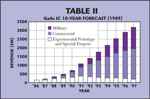
Table 2 GaAs IC 10-year forecast (1989).
Conclusion
What were the watershed moments in design software? The development of microstrip/stripline transmission line theory, and MIC and MMIC technologies, the GaAs FET and simulation models, the adoption of S-parameters and the network analyzer, two-port linear analysis, parameterization and optimization, development of distributed transmission line models, time-shared mainframe computers, the microprocessor and PC, the development of planar and 3D electromagnetic simulation, the development of harmonic balance, krylov-subspace, transient assisted harmonic balance, circuit envelope, netlist to artwork conversion software, the schematic editor, the integrated multi-tool workstation, the integrated design environment, C++ and object-oriented coding, back-annotated layout, the system simulator (time and frequency), dynamically-linked circuit, system and EM solvers, parallel processing, compute farms, domain decomposition, nonlinear devices characterization and X-parameters. Hardware and software evoevolution have always progressed together, hand-in-hand.
Part II
In Part II, our story continues with contributions from the people working in CAE/EDA today. As military spending winds down and cellular technology takes off, the software market goes through some fundamental changes. HP acquires EEsof; Ansoft acquires Compact, Applied Wave Research (AWR) and Computer Simulation Technologies (CST) enter the market; The MAFET program; EM and system tools make significant gains in capability and popularity; and automated design environments (ADS, Microwave Office, Ansoft Designer, Genesys and Microwave Studio) with integrated simulators, layout, EM and more take center stage all while playing a critical role in the wireless revolution.
Comments
Have some war stories from your early days of using, developing or supporting RF/microwave CAE software? We would love to hear from you. Contact the author at dvye@mwjournal.com.
References
1. http://smithsonianchips.si.edu/texas/radar.htm.
2. T. Hyltin, IMS 2008 Session, TH1E “History of MIC/MMIC Inventions,” http://www.mtt-tpms.org/cgi-bin/symposia_v4/sessiondisplay.cgi?Symposium_Name=IMS2008&sessiontodisplayid=TH1E&pointofcontact3;
3. http://www.microwaves101.com/encyclopedia/historyCAD.cfm.
4. http://en.wikipedia.org/wiki/Compact_Software.
5. D. Pescovitz, 1972, The release of SPICE, still the industry standard tool for integrated circuit design, http://www.coe.berkeley.edu/labnotes/0502/history.html.
6. http://www.mtt.org/awards/millenniummedals/besser.htm.
7. L.W. Nagel and D.O. Pederson, SPICE (Simulation Program with Integrated Circuit Emphasis), Memorandum No. ERL-M382, University of California, Berkeley, April 1973.
8. “A Heritage of Technology and Innovation: The History of Agilent EEsof EDA,” Gary Breed, available at http://eesof.viewmark.com/pdf/history_2001.pdf.
9. http://www.comsat-legacy.org/COMSAT%20Magazine/COMSAT%20Magazine,%2017.PDF.
10. Stiglitz and Resnick, Microwave Journal, MIMIC phase 1 Awards: Shocks and Aftershocks, September 1988.
11. http://en.wikipedia.org/wiki/Computational_electromagnetics.
12. http://physicsworld.com/cws/article/indepth/39209.
13. L. Besser and R. Gilmore, Practical RF Circuit Design for Modern Wireless Systems: Passive Circuits and Systems, Artech House Inc., Norwood, MA 2003.
14. S. Pavel, Partial Differential Equations and the Finite Element Method, John Wiley & Sons Inc., 2005.
15. http://people.engr.ncsu.edu/mbs/Publications/vitae_papers/1991/gilmore_steer_ijmmcae_I_1991.pdf.
16. K. Kundert and A. Sangiovanni-Vincentelli, “Nonlinear Simulation in the Frequency Domain, Computer-Aided Design of Integrated Circuits and Systems,” IEEE Transactions, Vol. 5, No. 4, October 1986, pp. 521-535.