Recently, with the rapid development and deployment of wireless communication systems, the miniaturization and performance improvement of wireless communication components have become increasingly necessary. In particular, the miniaturization of a filter, one of the core components in many radio frequency (RF) systems, has become a very important issue. Apart from three-dimensional filters, such as surface acoustic wave (SAW), ceramic or waveguide type filters, planar transmission line filters have generated a great deal of interest, due to their advantages as a planar circuit and their simplicity of fabrication, as well as their lower cost. As a result, their miniaturization has been widely investigated. Among planar transmission line filters, the ladder filters based on periodic structures,1 the pseudo-interdigital2 and hairpin filters3 using bent resonators, and the combline filters with lumped components,4 are a few examples. The previously mentioned filters have certain advantages as well as disadvantages. In the case of the ladder filter, a highly accurate full-wave electromagnetic simulation is required for its accuracy, and its possibility of miniaturization is limited. The pseudo-interdigital and hairpin filters also exhibit such limitations in size reduction. It is not straightforward to calculate the self- and mutual-capacitances for the combline filter with lumped components, and an accurate analysis of the combline structure is a required procedure. In view of these difficulties, this article proposes a new miniaturization method that is very simple because there is no need to calculate mutual-impedances and because the method is based on a simple parallel coupled-line filter and a small number of lumped capacitors and groundings.
Miniaturization Theory
Any transmission line within a specified accuracy range can be miniaturized into a transmission line having a higher characteristic impedance by using shunt capacitors.5 A parallel coupled-line can be considered as a linear superposition of even- and odd-mode equivalent circuits, and can be miniaturized with the method presented by Kim, et al.6 When the ?/4-long (electrical length ? = ??/4) conventional parallel coupled-line is miniaturized with the capacitors Ce and Co, as shown in Figure 1, the even- and odd-mode characteristic impedances, Z0e' and Z0o', and the lumped capacitances, Ce and Co, are obtained as follows:
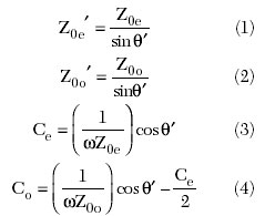
where
?' = electrical length of the miniaturized coupled lines.
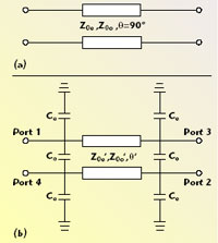
Fig. 1 Miniaturization of parallel coupled-line with capacitors; (a) conventional parallel coupled-line and (b) miniaturized parallel coupled-line with capacitors.
Since the parallel coupled-line filter consists of cascade combinations of parallel coupled-lines, the approach mentioned above can be further developed into a miniaturized filter. It is clear that the miniaturized filter based on the combination of the equivalent parallel coupled-lines requires roughly 6(N+1) capacitors for an Nth-order filter. When lumped capacitors are used at high frequencies, the effects of their parasitic elements become significant, and the miniaturization process reveals its inherent limitations. To mitigate this shortcoming, a simple and accurate new method is proposed, based on short-circuited components and a smaller number of capacitors.
The impedance as well as the admittance parameters of the open-ended parallel coupled line (OEPCL) and short-ended parallel coupled line (SEPCL), which have the same normalized even (Z0e)- and odd (Z0o)-mode characteristic impedances, are described by Jones and Bolljahn7
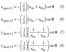
When the characteristic impedances of the coupled line are 50 ?, the normalized even-mode characteristic impedance is the inverse of that of the odd-mode — z0e = 1/z0o. Thus, the impedance matrix of the OEPCL is identical to the admittance matrix of the SEPCL, and as a result, each scattering matrix has the same magnitude but opposite phase values. The characteristic impedances of the coupled lines in the filter are close to 50 ?, and as a result, the equivalent magnitude characteristics can be achieved if the OEPCL is replaced with the SEPCL according to the above relations.
According to the described analysis, the number of capacitors used for miniaturization can be reduced. When ports 3 and 4 are grounded, there is no need to use the Ces connected to these ports; the Cos can be combined with the Ces connected at ports 1 and 2. Therefore, the SEPCL is miniaturized with only two capacitors. When this method is applied to an Nth-order filter, the number of lumped capacitors for miniaturization can be greatly reduced from 6(N+1) to (N+2). The final topology of the proposed miniaturized filter is shown in Figure 2.

Fig. 1 Miniaturized parallel coupled-line filter using capacitors and grounding.
It should be noted that the shunt capacitance, as well as the even- and odd-mode characteristic impedances of the filter, can be expressed as
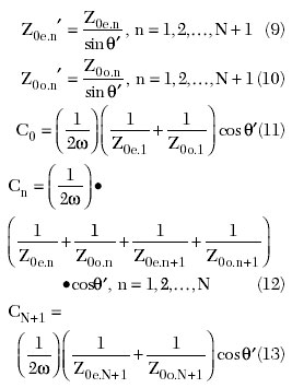
where
?' = electrical length of the miniaturized coupled line sections and ? is the center frequency.
The proposed approach can be applied to the design of an arbitrary length coupled-line filter and to reduce the number of lumped capacitors. Furthermore, due to the weakened symmetry of the filter topology, the harmonic responses are greatly suppressed. Also, note that the method can also be equally applied to the hairpin filter by bending its resonators.
Filter Design and Experimental Results
To examine the effectiveness of the proposed method, a miniaturized third-order Chebyshev filter with 0.5 dB pass band ripples is designed and fabricated for a center frequency of 900 MHz with an FBW of 10 percent. The even- and odd-mode characteristic impedances for the conventional filter with ?/2-long resonators and for miniaturized filters with a reduced number of lumped capacitances and grounding is summarized in Table 1. The even- and odd-mode characteristic impedances become larger as the size of the resonator becomes shorter.

For the design process, an ideal coupled line model from a commercial circuit simulator8 was employed; the simulation results are displayed in Figure 3. The insertion losses of the conventional open-ended and short-ended, as well as three types of miniaturized filters, show almost identical characteristics. It is also clear that with three different resonator lengths, ?/4, ?/8 and ?/16, the filter characteristics remain almost unchanged except for a slight decrease in bandwidth, which validates the proposed design procedure. Figure 4 shows a photograph of a miniaturized filter with ?/4-long resonators, fabricated on a Duroid (?r = 10) substrate. The measured characteristics of the miniaturized ?/4-long as well as open- and short-ended filters with l/2-long resonators have been compared. The results are shown in Figure 5. They show that the miniaturized filter based on the proposed method has the same pass band characteristics, while the second and third harmonics are effectively suppressed. An improvement in the high frequency skirt characteristics is also observed, which is due to the harmonic suppression. However, the insertion loss of the miniaturized filter in the pass band is slightly degraded by about 1 dB. This is partially caused by the finite quality factor of the capacitors used in the miniaturization.

Fig. 3 Simulation results.

Fig. 4 A fabricated filter miniaturized with ?/4-long resonators (?' = 45°).
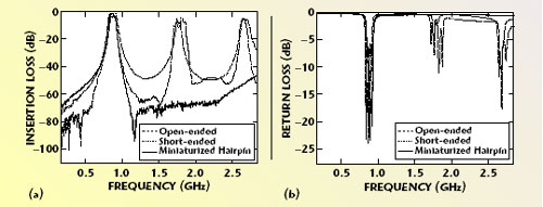
Fig. 5 Measured results for (a) insertion loss and (b) return loss.
Conclusion
This article proposes a miniaturization method for a parallel coupled-line filter using lumped capacitors and grounding. The method for calculating the values of the capacitors is also well documented. With this approach, the number of capacitors can be reduced to 1/6 of that of the conventional way. This is due to the fact that the SEPCL has identical S-parameters with the OEPCL except for the phase, which is reversed. Note that it is possible to reduce the length of the resonator to any arbitrary length with a very simple procedure. Moreover, the proposed method suppresses the harmonic responses of the filter due to the lumped capacitors and improves the high frequency skirt characteristics. The proposed miniaturization method can be applied not only to microstrip, but also to CPW and striplines, as well as any transmission line structures. Furthermore, the proposed method makes the filter fabrication as small as possible, when the filter is integrated in MMICs and LTCC-based circuits and systems.
References
1. J.S. Hong and M.J. Lancaster, “A Novel Microwave Periodic Structure — The Ladder Microstrip Line,” Microwave and Optical Technology Letters, Vol. 9, July 1995, pp. 207–210.
2. J.S. Hong and M.J. Lancaster, “Investigation of Microstrip Pseudo-interdigital Bandpass Filters Using a Full-wave Electromagnetic Simulator,” International Journal of Microwave and Millimeter-wave Computer-aided Engineering, Vol. 7, May 1997, pp. 231–240.
3. E.G. Cristal and S. Frankel, “Design of Hairpin-line and Hybrid Hairpin-parallel-coupled-line Filters,” 1971 IEEE MTT-S International Microwave Symposium Digest, Vol. 1, pp. 12–13.
4. G.L. Matthaei, “Comb-line Bandpass Filters of Narrow or Moderate Bandwidth,” Microwave Journal, Vol. 6, No. 8, August 1963, pp. 82–91.
5. T. Hirota, A. Minakawa and M. Muraguchi, “Reduced-size Branch-line and Rat-race Hybrids for Uniplanar MMICs,” IEEE Transactions on Microwave Theory and Techniques, Vol. 38, No. 3, March 1990.
6. Y.T. Kim, et al., “Design and Implementation of Lumped/Distributed-elements Direction Coupler for NMT 450 SYSTEM,” 2003 Asia-Pacific Microwave Conference Proceedings, Vol. 1, pp. 498–501.
7. E.M.T. Jones and J.T. Bolljahn, “Coupled-strip-transmission-line Filters and Directional Coupler,” IRE Transactions on Microwave Theory and Techniques, Vol. 2, April 1956, pp. 75–81.
8. Advanced Design System 2004A, Agilent Technologies Inc., 2005.
Seong-Sik Myoung received his BS degree in electronic engineering from Soongsil University, Seoul, Korea, in 2002, and his MS degree in electronic engineering from Yonsei University, Seoul, Korea, in 2004, where he is currently working toward his PhD degree. His interests include MMICs, compound- and Si-based semiconductors, and RF components and devices.
Jong-Gwan Yook received his BS and MS degrees in electronic engineering from Yonsei University, Seoul, Korea, in 1987 and 1989, respectively, and his PhD degree from the University of Michigan, Ann Arbor, MI, in 1996. He is currently an assistant professor at Yonsei University, where his research interests include the theoretical/numerical electromagnetic modeling and characterization of microwave/millimeter-wave circuits and components, very large scale integration (VLSI) and monolithic microwave integrated circuit interconnects and RF MEMS devices using frequency- and time-domain full-wave methods, the development of numerical techniques for analysis, and the design of high speed high frequency circuits with an emphasis on parallel/supercomputing and wireless communication applications.
