
As the size of components, boards and subsystems decreases, the connection interfaces often become a size limiting component so there is a need to reduce their footprint. There is also a need to increase the connection density in many existing systems or boards to get more data or signals in and out without changing the existing connection interface. A new high density RF interconnect (HDRFI®) has been developed and tested to meet this need and functions as a high performance connector from DC to 40 GHz.
This new connection system transfers high frequency signals through a unique planar interface. This planar interface removes the need for typical pin and socket connections by utilizing a z-axis elastomer to provide the electrical path between the mated connectors. The elastomer is made up of silicone, impregnated with gold plated stainless steel wires that are arranged on a 0.35 mm pitch. When compressed by the mating halves, the gold plated wires mechanically connect the two planar surfaces and create an electrical EMI barrier to provide excellent isolation. The result is a high density, high bandwidth, compact RF interconnect with a center-to-center spacing of 0.130” where the alignment of the connector is independent of the RF path.
Construction
The new system uses high frequency low loss coax cable and a unique patented interconnect system to transfer the signal thru the elastomeric planar connection system. The system allows for high frequencies to be transferred with minimal loss and reflections. Figure 1 shows the assembly cross-section for the coax contact.
Figure 1 Cross-section of coax contact.
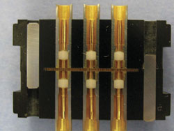
Figure 2 Cross-section of HDRFI connector.
These coax connections mate against the elastomeric interface to form the connection between the two connectors. Figure 2 shows the cross-section of two connectors and the elastomeric interface. There are no moving parts and only a low compression mating force is needed. The system eliminates stubbing and can be used differentially or single ended. The elastomeric interface is Fujipoly WSC series silicone rubber impregnated with gold plated stainless steel wires. The wires are in clusters that are made up of 3 to 6 wires and the clusters are spaced 0.35 mm apart. Figure 3a shows a cross-section view of the elastomer where the wires are flexing where the contacts are made. The center contact area and outside shield are indicated. Each wire is individually isolated from each other by the silicon insulator.

Figure 3 Cross-section of HDRFI elastomer (a) and metalized surface (b) showing wire clusters.
The elastomer has a metalized gold pattern on each side to connect to the coax pins on each connector, but the necessary isolation is kept between each connection due to the spacing of the clusters that are not connected to the surface pattern. The isolation between clusters is 100 MΩ minimum. Figure 3b shows the metalized pattern on the surface and wire ends that protrude through the silicone to make the connection.
Modeling
EM simulations were performed on a model of the contact and elastomer as a single coaxial assembly using Microwave Studio from CST. Figure 4 represents a cross-section parallel to the plane of the elastomer, and is an instantaneous image of the peak field strength in the medium at 25 GHz. The blue color, representing very low field strength, visible everywhere outside the contact shield, is evidence that interference and crosstalk are going to be very small. Modeling of an adjacent pair of signal lines yielded a crosstalk figure of below -100 dB.
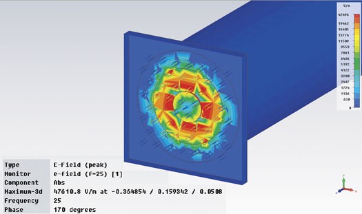
Figure 4 EM simulation of HDRFI cross-section.
Performance
RF measurements were performed on a mated pair of the high density coax connectors with HFF-1087 cable and SMP connectors at the ends to attach to the test leads of the network analyzer. The measured results show excellent transmission (-1.1 dB @ 5 GHz and -4.5 dB @ -40 GHz) and return loss (< 20 dB) values up to 40 GHz, as shown in Figures 5a and 5b, respectively. The plots of the HDRFI mated interface include two feet of 24AWG low loss coax and connector adapters. Figure 6 shows the measured isolation between adjacent connectors was -100 dB at 15 GHz and approximately -95 dB at 40 GHz. The connector was also tested for durability and was shown to have consistent attenuation (standard deviation of 0.05 dB up to 26 GHz) after more than 2000 mating cycles, four times more than a typical connector system, as shown in Figure 7.
Figure 5 Transmission (a) and return loss (b) measurements of HDRFI connectors.
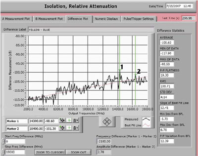
Figure 6 Isolation measurement of HDRFI connectors.

Figure 7 Durability test results of HDRFI connectors.
The connector also demonstrated very good signal integrity. The measured eye pattern data using the Tensolite HFF-1087 cable (coax contacts set as differential signals in a RF D-sub shell) is shown in Figure 8 based on the Double Speed Fibre Channel protocol at a length of eight meters without equalization.
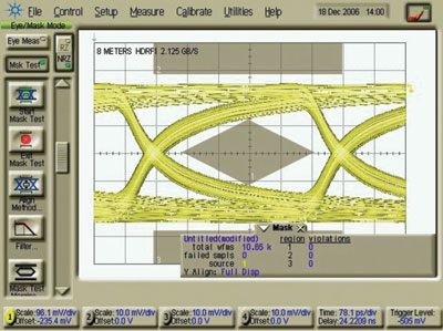
Figure 8 Signal integrity measurement of HDRFI connector.
Table 1 shows a summary of the electrical performance parameters for the HDRFI assembly. Table 2 shows mechanical specifications for this system and Table 3 shows the environmental testing performed.

Table 1 Electrical Performance Summary

Table 2 Mechanical and Environmental Specifications
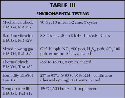
Table 3 Environmental Testing
The interconnect system has been used in high density connectors used in high speed digital and many RF applications that call for compact signal routing. Applications include broadband antennas for UAV/ground troop communication, signal intelligence, a phased-array radar program with over 20,000 signals per radar and even the complex harnessing used in some space-weary submarines.
Configurations
HDRFI is made as an assembly in three form factors: D-sub, circular and mezzanine. Custom configurations are also available. The assemblies can be used with a 26AWG coax for internal applications or 24AWG for external requirements.
The RF D-sub connector family is made in four different shell sizes and can be used in cable to cable, cable to board or board to board applications. Designed with high performance in mind, the insert arrangements are maximized to hold more impedance controlled size 16 type RF contacts than other typical D-sub connectors. The HDRFI RF contacts are press-in style and the connectors can accommodate standard D-sub backshells and mounting hardware. The mixed-signal D-sub connector family is a good solution to combine both power and high frequency RF contacts into a standard D-sub shell.
The circular connector family is made for high performance applications. The insert arrangements are maximized to hold more impedance controlled size 16 type RF contacts than any other circular connector on the market today. The product line consists of shell sizes 15 to 25 and is based on the D38999 specification. The HDRFI RF contacts are press-in style and the connectors can accommodate standard D38999 backshells and hardware.
The mixed-signal circular connector family is a perfect solution to combine both power and high frequency RF contacts into the same connector body. The product line consists of shell sizes 15 to 25 and is based on the D38999 specification. The signal pins are size 20, rated to 7 amps and are combined with the HDRFI RF contacts. All of the contacts are press-in style and the connectors can accommodate standard D38999 backshells and hardware.
HDRFI can be customized to fit almost any application, from custom board connectors, to insert arrangements that can have a common ground plane, to having each signal path isolated from each other. It is a high performance, high density connection solution for many applications from DC to 40 GHz.
 Christopher Tutt received his training while serving in the US Navy with a background in RADAR technology and fire control systems. He is currently a product manager for Carlisle Interconnect Technologies, St. Augustine, FL. He has been involved in cable, connector and cable assembly designs for 18 years. He currently holds five patents in the interconnect field.