
Metamaterials,1,2 with simultaneous negative permittivity and permeability, are promising materials for new types of microwave components. In metamaterials, the waves are propagating with anti-parallel phase and group velocities, as demonstrated by backward waves.3 Recently, an extended transmission-line approach to metamaterials, low loss and broadband structures was proposed4–6 and studied by different groups.7–10 A novel coupled-line directional coupler, using left-handed (LH) transmission lines, was also proposed and studied.11–14 A symmetric LH/LH structure, used in a backward coupler with an arbitrary coupling level and broad bandwidth, has been fully explained.13
In this article, a symmetric right-/left-/right-handed (RH/LH/RH) power divider, a symmetric LH/RH/LH power divider and an asymmetric LH/RH/LH power divider are proposed, which consist of conventional microstrips and composite right-/left-handed (CRLH) transmission lines with L-C lumped-elements. The power dividers have multiple-port outputs, broad bandwidths and arbitrary coupling levels. If the loaded L-C elements in the two CRLH lines have different values, the LH/RH/LH power divider can have different frequency bands for each output port. At the same time, the lumped-elements offer some significant advantages: the circuit is more compact in size, the material parameters can be tuned and the method of fabrication is easy. This article presents first the characteristics of one-dimension metamaterials. A symmetric RH/LH/RH (or LH/RH/LH) power divider and an asymmetric LH/RH/LH power divider are then described and their simulated performance, obtained from the circuit models, are compared to experimental results.
The Characteristics of One-dimension Metamaterials
L-C lumped-elements are loaded on a conventional microstrip to fabricate the CRLH transmission line. Figure 1 shows the structure of the CRLH transmission line. The LH line is fabricated on a 1.6 mm thick FR-4 substrate with a dielectric constant ε = 4.75, and the 50 Ω microstrip transmission-line segments are 2.945 mm wide. All the measurements were carried out with an Agilent 8722ES vector network analyzer.
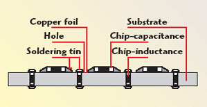
Fig. 1 Structure of the CLRH transmission line.
Figure 2 shows the S21 parameter of the CRLH line with a different number of cells. Each cell consists of a microstrip loaded with lumped-elements, C = 5.1 pF, L = 4.7 nH; the length of each cell is d = 7 mm. As the number of cells is increased, the attenuation in the bandgap increases. In the range considered, the attenuation in the bandgap is approximately 2 dB/cell. The group velocity and phase velocity can be obtained from the S-parameters and their phase. Figure 3 shows the group velocity and phase velocity in the passband of a line with 20 cells.

Fig. 2 S21 of the CLRH line for different numbers of cells.
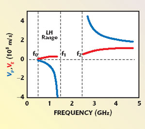
Fig. 3 Phase and group velocities in the passband.
By comparing the two figures, it can be observed that the left-handed range with anti-parallel phase and group velocities is beginning at the cut-off frequency (f0 = 1/4π√CL) of the high pass structure to the bandgap; the right-handed range with parallel phase and group velocities is above the bandgap. The bandgap can also be found (from f1 = 1/2π√CL0d, to f2 = 1/2π√LC0d, where C0 and L0 are the distributed parameters of the microstrip) corresponding to a zero averaged refractive index between the left-handed range and the right-handed range, as first indicated by Reference 15. Such zero–n bandgap differs fundamentally from the usual bandgap induced by the Bragg scattering. That is, it is independent of scaling, and is insensitive to the disorder, incident angle and polarization.15,16
The Symmetric and Asymmetric Power Dividers
The Symmetric Trisecting Power Dividers
The trisecting power divider with a symmetric structure (RH/LH/RH) is shown in Figure 4. It consists of two conventional microstrips (ports 3 to 4 and ports 5 to 6) and one CRLH transmission line (ports 1 to 2) between the microstrips. When a signal is applied to port 1, the power is coupled to ports 3 and 5 equally, and ports 4 and 6 are isolated. The unit cell circuit model used for simulation is shown in Figure 5. The measured S-parameter results, shown in Figure 6, are in good agreement with the simulated results shown in Figure 7. From 2.1 to 2.7 GHz, the coupled power (ports 3 and 5) and the through power (port 2) are 4.77±1 dB, with a fractional bandwidth of approximately 25 percent.

Fig. 4 The six-cell trisecting power divider with a symmetric structure (RH, LH,RH).

Fig. 5 Unit cell circuit model.
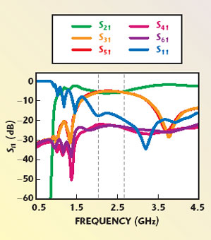
Fig. 6 Measured results for the six-cell trisecting power divider with a symmetric structure (RH, LH, RH).

Fig. 7 ADS simulated results for the sixcell trisecting power divider with a symmetric structure (RH, LH, RH).
The symmetric structure power divider can also be designed with a microstrip between two CRLH lines (LH/RH/LH). Figure 8 shows the LH/RH/LH symmetric structure power divider. The measured S-parameter results shown in Figure 9 are in good agreement with the simulated results shown in Figure 10. These results are similar to the ones for the RH/LH/RH power divider.
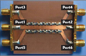
Fig. 8 The six-cell trisecting power divider with a symmetric structure (LH, RH, LH)
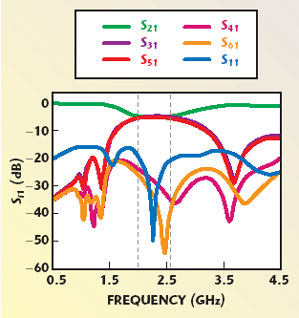
Fig. 9 Measured results for the six-cell trisecting power divider with a symmetric structure (LH, RH, LH).

Fig. 10 Simulated results for the six-cell trisecting power divider with a symmetric structure (LH, RH, LH).
The Asymmetric Power Dividers
The asymmetric power divider has the same physical structure as the symmetric LH/RH/LH power divider, but the loaded L-C elements in the two LH transmission lines have different parameters. The asymmetric power dividers can have different frequency bands for each output port.
An asymmetric power divider was simulated and fabricated with loaded elements C1 = 5.1 pF, L1 = 8.2 nH in one CRLH transmission line (ports 3 to 4) and C2 = 1.0 pF, L2 = 1.8 nH in the other CRLH transmission line (ports 5 to 6). The gap between the lines is 0.2 mm and the coupled length is 100 mm. The CRLH transmission line consists of 20 cells with a length of 5 mm, which is much longer than for the symmetrical power dividers. As a signal is input to port 1, the power couples to port 3 and port 5 in different frequency bands, and ports 4 and 6 are isolated. The measured S-parameter results shown in Figure 11 are in good agreement with the simulated results shown in Figure 12.

Fig. 11 Measured S-parameters for the asymmetrical power divider.

Fig. 12 Simulated S-parameters for the asymmetrical power divider.
Discussion
This power divider works on the basis of a mixed conventional microstrip and composite right-/left-handed backward-wave directional coupler.14 Here, the composite right-/left-handed transmission line is called one-dimension metamaterial. Compared with the traditional microstrip coupler, the difference is obvious. The coupler based on metamaterials has a higher coupling and a larger bandwidth. The coupling between a microstrip line and a one-dimension metamaterial line is much tighter than the coupling between two traditional microstrip lines. A possible mechanism may be that the group velocity in this metamaterial and between a microstrip line and a one-dimension metamaterial line is much slower than in a normal media. Shadrivov, et al.17 supposed that there are vortexes between the LH and RH lines, resulting in a lower effective coupling length and lower group velocity. In this case, more energy can be transferred between the microstrip line and the one-dimension metamaterial line, so that it shows a tighter coupling than in a traditional microstrip coupler.
Conclusion
One-dimensional metamaterials, using L-C lumped-elements, have a broad left-handed passband, with anti-parallel phase and group velocities. Symmetric and asymmetric structure power dividers were made, which show superior characteristics: broadband, multi-ports and arbitrary coupling level. The simulations and measurements all show their superior characteristics.
Acknowledgment
This project was supported by the 973 Project (Grant No. 2001CB 610406), by the NSFC (Grant No. 50477048) and by the Shanghai Science and Technology Committee. One author, Fuqiang Liu, would like to acknowledge the support of the 973 Project (Grant No. 2004CB719802).
References
1. V.G. Veselago, “The Electrodynamics of Substances with Simultaneously Negative Values of e and m,” Soviet Physics Uspekhi, Vol. 10, No. 4, 1968, pp. 509–514.
2. R.A. Shelby, D.R. Smith and S. Schultz, “Experimental Verification of a Negative Index of Refraction,” Science, Vol. 292, 2001, pp. 77–79.
3. A. Grbic and G.V. Eleftheriades, “Experimental Verification of Backward-wave Radiation from a Negative Refractive Index Metamaterial,” Journal of Applied Physics, Vol. 92, No. 10, 2002, pp. 5930–5935.
4. C. Caloz and T. Itoh, “Application of the Transmission-line Theory of Left-handed (LH) Materials to the Realization of a Microstrip ‘LH Line’,” 2002 IEEE AP-S International Antenna and Propagation Symposium Digest, Vol. 2, pp. 412-415.
5. A.K. Iyer and G.V. Eleftheriades, “Negative Refractive Index Metamaterials Supporting 2-D Wave,” 2002 IEEE MTT-S International Microwave Symposium Digest, Vol. 2, pp. 1067–1070.
6. A.A. Oliner, “A Periodic Structure Negative Refractive Index Medium without Resonant Elements,” 2002 IEEE AP-S/URSI International Antenna and Propagation Symposium Digest, p. 41.
7. C. Caloz, H. Okabe, T. Iwai and T. Itoh, “Transmission-line Approach of Left-handed (LH) Materials,” 2002 USNC/URSI National Radio Science Meeting Digest, p. 39.
8. O.F. Siddiqui, S.J. Erickson, G.V. Eleftheriades and M. Mojahedi, “Time-domain Measurement of Negative Group Delay in Negative Refractive Index Transmission-line Metamaterials,” IEEE Transactions on Microwave Theory and Techniques, Vol. 52, No. 5, June 2004, pp. 1449–1454.
9. G.V. Eleftheriades, A.K. Iyer and P.C. Kremer, “Planar Negative Refractive Index Media Using Periodically L-C Loaded Transmission Lines,” IEEE Transactions on Microwave Theory and Techniques, Vol. 50, No. 12, December 2002, pp. 2702–2712.
10. D. Zhang, Y. Zhang, L. He, H.Q. Li and H. Chen, “One-dimension Metamaterials by Using of Lumped-elements L-C,” PECS-V International Symposium Digest, March 2004, p. 96.
11. R. Islam and G.V. Eleftheriades, “A Planar Metamaterial Co-directional Coupler that Couples Power Backwards,” 2003 IEEE MTT-S International Microwave Symposium Digest, Vol. 1, pp. 321–324.
12. C. Caloz, A. Sanada, L. Liu and T. Itoh, “A Broadband Left-handed (LH) Coupled-line Backward Coupler with Arbitrary Coupling Level,” 2003 IEEE MTT-S International Microwave Symposium Digest, Vol. 1, pp. 317–320.
13. C. Caloz, A. Sanada and T. Itoh, “A Novel Composite Right-/Left-handed Coupled-line Directional Coupler with Arbitrary Coupling Level and Broad Bandwidth,” IEEE Transactions on Microwave Theory and Techniques, Vol. 52, 2004, pp. 980–992.
14. C. Caloz and T. Itoh, “A Novel Mixed Conventional Microstrip and Composite Right-/Left-handed Backward-wave Directional Coupler with Broad and Tight Coupling Characteristics,” IEEE Microwave and Wireless Components Letters, Vol. 14, No. 1, 2004, pp. 31–33.
15. J. Li, L. Zhou, C.T. Chan and P. Sheng, “Photonic Bandgap from a Stack of Positive and Negative Index Materials,” Physical Review Letters, Vol. 90, No. 8, 2003, p. 083901.
16. H.T. Jiang, H. Chen, H.Q. Li, Y.W. Zhang and S.Y. Zhu, “Omni-directional Gap and Defect-mode of One-dimensional Photonic Crystals Containing Negative-index Materials,” Applied Physics Letters, Vol. 83, No. 26, 2003, pp. 5386–5388.
17. I.V. Shadrivov, A.A. Sukhorukov and Y.S. Kivshar, “Guided Modes in Negative Refractive-index Waveguides,” Physical Review E, Vol. 67, No. 5, 2003, p. 057602.