The Wilkinson divider has long been popular with RF designers. In recent years, off-the-shelf, surface-mount technology (SMT) components of this type have become available and provide tremendous cost savings in high volume pick and place manufacturing. Some of its applications are found in power amplifier design and modern communication systems. Many applications employing the Wilkinson structure cannot be enhanced by the use of any available surface-mount or tab-contact component solution. However, through the use of new materials and manufacturing processes with new design techniques, these SMT power dividers provide better performance and wider applicability. These innovative, ceramic-based planar components now permit the realization of smaller and more integrated power amplifiers that can tolerate worse internal and external source and load mismatches.
The Wilkinson power divider has been well documented and used for many years as a building block in many RF and microwave splitting and combining networks. In power amplifier applications, the power divider allows single, large and expensive, high power amplifiers to be replaced with several, smaller and lower cost, power amplifiers. In addition, this power dividing/combining technique takes advantage of the linear operating region of the high power amplifiers, thus reducing intermodulation distortion.

The Wilkinson in-phase divider utilizes ?/4 transmission lines for impedance matching and an isolation resistor connected between each end of the l/4 section(s). In an N-way power divider, the power division depends on the number N of output ports. The magnitude of the power division is calculated using the equation 10log(1/N). The use of the resistors allows the ports to be matched. In addition, it isolates the output ports from one another at the center frequency.
When used as a power divider, the input signal is split into signals of equal amplitude and phase at the output ports. As a result, each terminal of the isolation resistor will be at the same potential and, consequently, no potential difference and no voltage drop. A mismatch at one of the output ports will not affect the other outputs. This is due to the 180° phase difference when the reflected signal appears at the opposite end of the isolation resistor. On the other hand, combining signals of unequal magnitudes will cause a voltage drop across the resistor, thus dissipating power.

The general performance characteristics of a power divider are isolation, amplitude balance, phase balance, VSWR, power handling capability and insertion loss. As an indication of high performance, a power divider has a typical isolation of 20 dB and the higher the isolation, the less chance of leakage between the output ports. Generally, the isolation will degrade at higher frequencies.
Amplitude and phase balances, sometimes referred to as amplitude and phase tracking, are also important indications. These are simply the amplitude and phase differences between the powers at the output ports. Amplitude balance typically increases with the number of output ports. The VSWR indicates how well the input and output ports are matched to each other and to external connections. In addition, the power handling capability is of high importance to the designer. The rating is usually given for matched conditions or matched power rating. For an unmatched system, the power handling is dependent upon the internal resistors used. Wilkinson power dividers are typically fabricated as a printed structure on Teflon-based material using chip resistors. In recent years, SMT versions have become readily available. The latest generation of SMT Wilkinson power dividers, fabricated on ceramic substrates, has recently become available and provides tremendous increases in performance, compared to SMT power dividers of previous generations. By utilizing a ceramic substrate, these products allow for higher thermal dissipation as opposed to those created with Teflon-based materials. Table 1 illustrates the power performance of the new power dividers under different matching conditions.

Two-way Power Dividers
The HybriX“ family of the SMT high power dividers is built on alumina, using thick film resistors and advanced screen-printing techniques, allowing better performance and wider applicability. In addition, smaller and more integrated circuits can be realized. These new generations of SMT high power dividers provide very low insertion loss, excellent return loss, very low VSWR, higher thermal dissipation and high power handling capacity up to 50 W. Typical measured S-parameter data for a two-way divider are shown in Figures 1 and 2.
Three-way Power Dividers

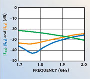
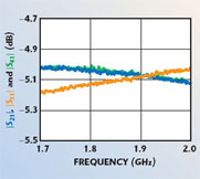
A single-stage three-way device can facilitate the development of power amplifiers with lower loss and more compact layouts. The three-way Wilkinson dividers in this new family of products are fabricated as completely planar microstrip structures. Typical measured RF performances for the HybriX three-way power divider, within the frequency range from 1.7 to 2 GHz, are shown in Figures 3 to 5. For these measurements, all the devices were operated as power dividers, that is, port 1 was the input and ports 2, 3 and 4 were the outputs. The test fixture dissipation and mismatch losses have not been de-embedded from these measured results. When referenced to 50 ?, the total loss of the test board is approximately in the range of 0.08 to 0.15 dB.
Four-way Power Dividers
The four-way power dividers expand the product line offering and are designed using the same design and process methodology as the three-way dividers described earlier. The RF performances for the four-way, in-phase power dividers are similar to those of the other dividers. To that end, they have a very low insertion loss, excellent isolation, low VSWR, high power rating, excellent thermal dissipation, and very good amplitude and phase balance.
High Power Testing

These high power SMT power dividers were tested by Modelithics Inc. to determine their power handling capabilities. The test conditions were as follows: The power divider was tested at increasing discrete power levels, each of 15 minutes duration. The base plate was held at a constant temperature of 85°C during the measurement. The S-parameter measurements were made between every increase in power level. The base temperature was monitored using a temperature probe, and the resistor temperature using an IR camera system. The parts met or exceeded the rated power.
Conclusion
Power dividers are commonplace in the RF world. Through the use of new materials and manufacturing processes together with new design techniques, power dividers have been reinvented. The latest generation of SMT high power dividers provides excellent isolation, low VSWR, low insertion loss, excellent return loss, high power rating, and very good amplitude and phase balance. In addition, their smaller size reduces the circuit area, thus allowing design flexibility.
