
In the typical GSM handset, the PA consumes approximately 40 percent of the energy stored in the battery during one discharge cycle. For this reason, the handset architect must use care in selecting a PA that will provide the most efficient means of generating the required transmitted RF power while using the least amount of energy from the battery.
Handset designers consider several key performance parameters when selecting a PA for GSM handset applications. Maximum output power and peak power efficiency are two of these key parameters. Because talk time, based on one battery charge cycle, is very important to the cell phone end user, the handset designer may select a PA that has the best peak power efficiency (or lowest current consumption at peak power). Though peak power efficiency is a good indicator of the PA impact to talk time, it does not tell the whole story.
In a GSM network, the handset does not always operate at maximum output power. In fact, the handset only operates at maximum output power about seven percent of the time. Probability density function (PDF) curves have been derived by the service providers to understand the probability versus transmit power level relationship for handset operating under real-life conditions.
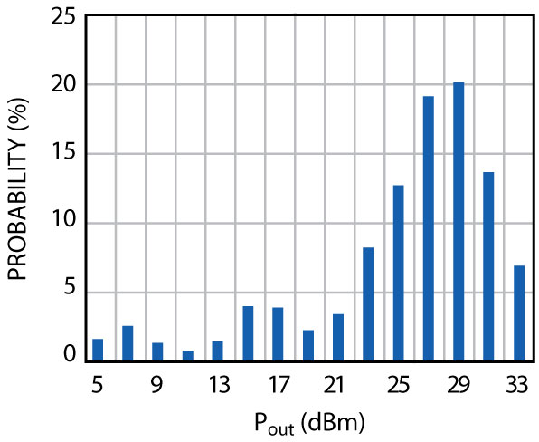
The Class 4 GSM900 band PDF curve, shown in Figure 1, illustrates the percentage of time that the handset is expected to be transmitting for each power control level (PCL) between 5 and 33 dBm. This relationship shows that almost 40 percent of the time the handset will be transmitting at 4 or 6 dB below the maximum output power. Knowing that backed-off transmit power outweighs peak power in actual usage, the opportunity for talk time improvements exists using intelligent power management which improves backed-off PA efficiency.
The RF power amplifier is designed to meet a specified maximum output power level given a certain minimum voltage from the battery. When the PA is not transmitting at maximum output power or when the battery is fully charged, the PA will not be operating at its most efficient point unless power management techniques are used. Power management is implemented through the use of a DC-to-DC buck converter, which ideally steps the battery voltage down without dissipating power in the form of heat. The DC-to-DC converter conserves energy by using a switching function that only draws current from the battery part of the time, thereby reducing the overall current drawn from the battery. The pulsed voltage on the converter output is filtered through a large LC filter network creating a new lower DC voltage. The DC-to-DC converter is properly controlled to set the PA collector voltage in order to establish the proper output power level.

Figure 2 shows a plot of the average battery current consumption for two different transmit modules (TxM). This data was collected at 12.5 percent duty cycle, so peak current would actually be eight times higher. The TxM is a PA plus switchplexer that connects directly to the antenna. TxM1 has a standard PA, which is controlled by a low dropout (LDO) power control circuit, while TxM2 has the same standard PA but uses a DC-to-DC converter as the power control method. The LDO power control method uses a FET to set the proper PA collector voltage for the required RF output power level. The FET acts as a variable resistor, which drops any extra DC voltage and dissipates power in the form of heat. The DC-to-DC converter power control method uses a pulse width modulator (PWM) to control the PA collector voltage. The PWM reduces the pulse width to reduce the DC-to-DC converter output voltage. Since current is drawn from the battery only during the on time of the PWM, the battery current consumption is substantially lower than that of the LDO power control method. The plot shows the dramatic effects on battery current consumption when using the DC-to-DC converter method of power control on a PA. TxM2 average current consumption is more than 31 mA lower than TxM1 for the power levels with the highest operating probability. Figure 3 illustrates the average current drawn from the battery based on the percentage of time the handset is transmitting at each power level.

To show the effects that this new power management technique has on the talk time performance of the GSM handset, an experiment was done to simulate a full battery discharge cycle of an 850 mA lithium ion battery in a simulated phone environment. For this experiment, the current consumption drawn by everything in the phone minus the PA was set at 100 mA continuous draw. This condition was simulated using a PA connected directly to the battery and biased to operate in idle mode at 100 mA. The transmitting TxM was also connected to the battery and operated over the PDF curve in 15-minute cycles. The PDF curve was used to set the percentage of time during the 15-minute cycle that the PA transmitted at each power level. For example, at output power level 29 dBm the probability is 20 percent, so the time spent transmitting at 29 dBm was three minutes (20 percent of 15 minutes) before going to the next operating power level. The test program repeated the 15-minute PDF cycle until the battery voltage dropped below 3.0 V. At that point, the time was recorded. After testing both TxM1 and TxM2, the results proved that TxM2, which used the DC-to-DC converter, operated one hour and 11 minutes longer than TxM1. That is a 21 percent improvement in handset talk time. The actual talk time results, based on operation at 12.5 percent duty, are shown in Figure 4.

An interesting point to notice when examining maximum RF output power current consumption is that TxM1 had slightly lower current consumption at the same peak power level. Based on the old train of thought about only looking at the peak power efficiency, TxM1 should have enabled the handset to operate with longer talk time than TxM2. This, however, was not the case. Even though peak power efficiency is still an important parameter to consider when selecting a PA to maximize talk time, proper transmitter power management can have a more substantial effect on talk time.
Like the GSM system, the (W)CDMA system also has a PDF curve for their typical network, which estimates the probability of the handset transmitting at a specified power level. Figure 5 shows the PDF curve for a typical CDMA system operating in two different environments, urban and suburban. In the CDMA case, the handset output power levels with the highest probability occur around –3 dBm. Since the most probable operating power level occurs so far below the +24 dBm maximum output power level, the handset architect must carefully design the transmitter section to focus on minimizing current consumption at the lower power levels in order to optimize talk time.

Once again, the best efficiency enhancement solution for minimizing battery current versus power level is to use a DC-to-DC converter for PA collector voltage control. In a WCDMA system, the PA is required to be linear. In order to maintain linearity, the DC collector voltage must be sufficiently high enough to accommodate the RF signal voltage swing. To achieve the most efficient transmitting system, the DC collector voltage should maintain the PA just slightly beyond the onset of gain compression. WCDMA power amplifiers are capable of transmitting a 0 dBm linear RF signal at a collector voltage of 0.6 V. A DC-to-DC converter supplying 0.6 V from a 3.6 V battery would reduce battery current consumption by 5/6 if the converter was 100 percent efficient. For the case of a standard fixed gain PA, which typically operates at 60 mA at 0 dBm, the current consumption would be reduced to 10 mA. Unfortunately, the converter is not 100 percent efficient, so the current consumption savings will be slightly less. DC-to-DC converters usually exhibit efficiencies in the mid 90 percent range under heavy load. A heavy load occurs when the DC-to-DC converter is sourcing current greater than 50 mA at a voltage level close to 3 V. Having high converter efficiency under heavy load is important to maintain overall PA plus converter system efficiency. In the WCDMA handset however, the PA is typically operating at a light load condition due to higher probabilities for lower power levels. The converter light load operating condition is usually considered to be at an output voltage below 1 V and sourcing current under 50 mA. A typical DC-to-DC converter will, at best, be 50 percent efficient under these operating conditions unless special design techniques are incorporated to improve light load efficiency. Even at a converter efficiency of 50 percent, the DC-to-DC converter solution still provides substantial current reduction benefit. In the example demonstrated earlier, where the current consumption was reduced from 60 to 10 mA with a 100 percent efficient converter, the 50 percent light load efficient converter would still reduce the current from 60 to 20 mA. For a WCDMA handset, the transmitter architect should look closely at the DC-to-DC converter specification for light load performance because in many cases these operating conditions are not included in the data sheet.

Additional current consumption savings can be achieved if the PA includes an analog bias control circuit. In this configuration, the PA base bias is reduced versus power since the PA does not require high collector current in order to remain linear at low power levels. Analog bias controlled WCDMA power amplifiers have been shown to operate linearly with as low as 20 mA quiescent collector current. At 0 dBm, the PA rectified current is only slightly above this quiescent current level. A simple example can demonstrate the reduction of battery current consumption when an analog bias control PA is operated with a DC-to-DC converter. An analog bias control PA operating at 0 dBm at about 24 mA of current would still only need 0.6 V collector voltage. The six times reduction in voltage from the DC-to-DC converter would result in a 5/6 reduction in the current consumption from the battery dropping it down to 4 mA with an ideal converter. Even with the converter at 50 percent efficient, the current consumption would still only be 8 mA.
Figure 6 illustrates measured results of the current drawn from the power supply when using the same WCDMA PA and utilizing different methods of power management. This chart focuses on the highest probable PA operating power levels in a handset and demonstrates the reduction in battery current consumption that can be achieved when using these various power management techniques. The 0 dBm PA operating power was chosen as the reference point because this would be the highest probable PA power level after considering approximately 3 dB of insertion loss in the handset between the PA and antenna. At 0 dBm, this chart illustrates that the DC-to-DC converter power management technique provides the biggest impact on the reduction of battery current consumption with a 79 percent reduction in current versus the PA with no power management. Additional current consumption reduction is achieved when combining the DC-to-DC converter with analog bias control resulting in an 88 percent reduction in current consumption. In a WCDMA handset, a PA operating with no power management can consume up to 40 percent of the available battery energy during one discharge cycle. With the use of intelligent power management and the potential 88 percent reduction in current consumption, the PA contribution to the energy consumed during the discharge cycle can be dramatically reduced.
Conclusion
This article has discussed the transmitter section of the handset and how the PA current consumption affects the handset talk time through one battery charge cycle. Although the PA peak power efficiency is still an important parameter to consider, this article has illustrated through measured results the need for intelligent power management in the handset transmitter section. Utilizing a DC-to-DC converter to properly manage the DC power to the PA is beneficial in both GSM and WCDMA handsets resulting in dramatic reduction in current consumption and thereby increasing the handset talk time. Along with the improvement to handset talk time, the DC-to-DC converter also provides another less recognized benefit in the form of less heat being generated by the PA. The DC-to-DC converter provides an optimal DC environment for the PA to operate with reduced power dissipation and thereby lower operating temperatures.
Steve Egolf graduated with his BSEE degree from West Virginia University in 1987. He is currently employed at RFMD as a staff level application engineer supporting power amplifier products. He has been in the application role for the past seven years. Prior to RFMD, he worked 13 years as a hardware design engineer at Northrop Grumman Corp. developing modules for high power radar transmitters.