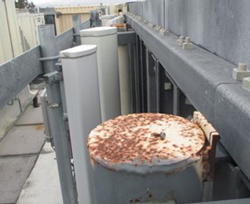
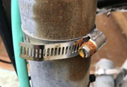
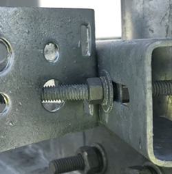
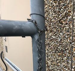
The root causes of PIM include poor metal contacts, corroded joining surfaces or loose mechanical connections. These defects can behave like non-linear elements, mixing the signals to generate PIM. Figures 3a to 3f, courtesy of Kaelus, illustrate examples of potential PIM sources.

Figure 3c Rusted metal and a loose screw on top of the drum.

Figure 3d Rusted metal and inadequate metal-to-metal contact.
The challenge intensifies on a single tower mast where multiple frequencies and technologies coexist. In this case, each additional signal increases the probability of PIM interference. This scenario, known as cross-band PIM, becomes a significant issue as various transmit signals from different frequencies or radios mix externally, creating substantial interference within the receiver bands. There are many possibilities for this interference. For instance, when collocating 700 MHz (Band 12), 850 MHz (Band 5) and PCS (Band 2) antennas, the third-order intermodulation product could generate intermodulation products that fall within the CBRS band. Another example involves the collocation of the 700 MHz (Band 12) and AWS (Band 4), potentially generating PIM in the CBRS band.

Figure 3e Poor metal-to-metal contact.

Figure 3f Metal chain makes intermittent contact with the pole.
While TDD was initially thought to be less susceptible to PIM due to the distinct transmission and reception time slots, the colocation of multiple TDD and FDD systems has shown that PIM can still pose a significant problem. Signals from nearby TDD and FDD transmitters can mix and generate PIM that impacts nearby receivers. Figure 4 shows the intermodulation profile from Figure 2 with a nearby TDD signal added. This issue underscores the complexity of managing PIM in environments dense with various signal types. It emphasizes the need for meticulous planning and deployment strategies to mitigate PIM's adverse effects on network performance.

Figure 4 Intermodulation products with TDD and FDD signals.
Managing PIM effectively requires good design and installation practices to minimize sources of non-linearity. It also requires ongoing monitoring and maintenance to ensure potential PIM sources do not degrade over time. The introduction of many frequencies and the technological diversification on a single base station mast can create a "PIM nightmare," necessitating sophisticated solutions and careful engineering to maintain optimal network performance.
SYNCHRONIZATION OF TDD NETWORKS
TDD synchronization can also lead to significant interference in 5G networks. Precise timing is required in TDD systems, where a single frequency band is shared for uplink and downlink communications to prevent signal overlap and subsequent interference. Misalignments in timing slots, often called timing issues, can cause signal overlap, leading to substantial network inefficiency. Collocating multiple operators or technologies can exacerbate these synchronization challenges and introduce misconfiguration or errors, resulting in network disruptions. These complexities necessitate sophisticated troubleshooting and synchronization techniques to ensure optimal network performance and reliability in dense, dynamic 5G environments.
OTHER INTERFERENCE
Beyond PIM and synchronization challenges, 5G networks are susceptible to a variety of other interference sources. These include emissions from other electronic devices, interference issues at country borders where signal overlap may occur due to differing regulatory standards and even disruptions from atmospheric conditions or topographical features that can reflect or distort signals. Each of these sources can complicate network operations, demanding sophisticated troubleshooting techniques to identify and mitigate the adverse effects efficiently and ensure robust network performance.
Effectively detecting interference in the 3.5 GHz spectrum requires filtering out adjacent bands and amplifying the signal to detect weak yet problematic interference or PIM signals. For instance, while troubleshooting a site equipped with CBRS radios in collocation with C-Band equipment, specific filters are needed to pass the CBRS signal and attenuate the C-Band signal. This approach ensures that only relevant frequencies are analyzed, thereby improving the accuracy and efficacy of interference detection.
INDUSTRY TRENDS
PIM Detection Methods: Traditional PIM testing utilizes two CW tones per the IEC 62037 standard. This enables RF technicians to verify the PIM levels of components to specifications. Although this method is effective, it is not well-suited for cross-band and multiple-tone PIM testing, which may limit its applicability in complex scenarios. An emerging alternative involves monitoring the CPRI link for an increased noise floor and potential PIM signatures on the uplink. While this method can detect the presence of interference, it provides little insight into resolving the underlying issues, thereby presenting challenges for comprehensive troubleshooting.
5G Trends: The evolution of 5G to various frequency bands, different modulation techniques (TDD versus FDD) and from modular to integrated systems have all influenced how interference is managed. These trends necessitate continual adjustments in interference mitigation strategies.
A SOLUTION
While it may seem straightforward, identifying and analyzing the interference is the first step toward reducing or eliminating network interference. The block diagram for a simple measurement system is shown in Figure 5. As the images in Figure 3 have shown, PIM interference can be influenced by the deployment environment, so it is worthwhile to measure signals in the field rather than in a lab environment. The system of Figure 5 shows battery operation to accommodate field testing.

Figure 5 Interference detection and measurement system.

Figure 6 MCV interference detection and monitoring toolset.
To address these requirements, MCV has tailored a solution kit that provides a comprehensive, portable, versatile set of tools for detecting and analyzing network interference. The system shown in Figure 5 relies on a spectrum monitor, which MCV does not supply. The components in this kit target applications in C-Band, CBRS, DoD, ESR and FAA bands. This kit from MCV is shown in Figure 6.
Maximizing the effectiveness of this interference detection method depends on proper selection of the individual components:
Filters: Each filter must be tailored to the band of interest. It is important to keep insertion loss low to minimize signal attenuation and maintain a high rejection level at the band edges. The sharp cutoff characteristics isolate the desired signal band from adjacent channel interference and ensure that only the intended frequencies are analyzed. This reduces the likelihood of aliasing from out-of-band signals. These filters should also be lightweight and rugged, suitable for various environmental conditions in the field.
LNAs: As described, intermodulation products will occur above and below the frequency range of the test signals, so the LNAs should have an operating frequency range that captures the interfering signals of interest. This may result in LNAs that operate at high frequencies with wide bandwidths. The LNA gain must also substantially increase signal strength with minimum signal distortion to amplify weak signals often lost in areas with high path loss. The LNA must also have a low noise figure to maximize the system's dynamic range and signal integrity.
Antennas: The antenna follows the same frequency range considerations as the LNA. It must operate at a high enough frequency with enough bandwidth the capture all the intermodulation signals of interest. It must also have sufficient gain to ensure these signals of interest have adequate signal strength. The antenna should also have enough front-to-back ratio to enhance directional sensitivity and minimize interference from the back side. This will also improve the directional accuracy, enabling the interference source to be more precisely located in densely populated network environments.
CONCLUSION
While beneficial, the advancement of 5G networks introduces significant interference challenges that can undermine network performance. While this is especially true of 5G networks with more frequency bands, modulation and duplexing schemes that require tower-mounted radios to be even closer to each other, interference affects all networks in an increasingly congested spectrum environment. This article has demonstrated how intermodulation products created by other electronics and PIM effects can cause interference that degrades system performance. It has also described a simple system and the important attributes of those system components that can be used to detect and analyze the interference sources.

