

A low-profile single frequency multiple-input multiple-output (MIMO) microstrip patch antenna with elements that include dual U-shaped slots and notches is proposed for use in several applications, including vehicle-to-vehicle communication, WiMax and sub-6 GHz networks. The chief motivation, however, is the design of a vehicular antenna with minimal envelope correlation coefficient (ECC) for independent performance of the MIMO antenna elements. The elements are fabricated on an FR-4 substrate and the antenna exhibits a 150 MHz bandwidth at 3.5 GHz. The design, analyzed and simulated using CST software, is evaluated in terms of port separation, ECC, mean effective gain (MEG) and channel capacity loss (CCL). Measured results are in strong agreement with the simulations. The design successfully achieves the desired ECC value of less than 0.001 with a gain of greater than or equal to 5 dBi, which is extremely low when compared to ECC values reported in previous research.
5G automotive communications is a core concept of the intelligent transportation system. This system involves communication between vehicles and vehicle communication with roadside infrastructure, and it is a rapidly expanding sector. Real-time communication between infrastructure and automobiles is now possible because of advancements in wireless communications. These advancements result in applications to improve car safety and passenger communication with the internet.
Within the broader vehicle-to-everything (V2X) communications umbrella, the desire for vehicle-to-vehicle (V2V) communications has grown recently, driven by efforts to improve automobile vehicle safety. Various design choices, including the size and type of antenna, influence the performance of a V2V system. Some classic designs include monopole,1 slot2 and patch antennas.3
These antennas provide low profiles and simple structures but with narrow bandwidths and low coverage efficiencies. To enhance the bandwidth and enable the antenna to operate in two bands, a microstrip monopolar patch system4 may be used. However, the substrate’s excessive thickness results in increased size and it complicates the design process.
Ozpinar et al.5 developed a mmWave antenna to achieve broad bandwidth, high gain, high coverage and high radiation efficiency in a compact, low-profile structure. Although it has several advantages, the antenna is severely affected by high transmission, penetration and atmospheric propagation losses. Most importantly, it requires high gain radiation beams.
To overcome these issues, systems on modern vehicles employ MIMO techniques. A MIMO system uses multiple antennas for both transmission and reception. This architecture enables the MIMO system to enhance bandwidth, data rate and throughput without altering transmit power or the frequency band of operation.
MIMO systems also have the advantages of high dependability and low latency in an environment with strong electromagnetic scattering. They support operation in LTE/5G sub-6 GHz, WLAN and V2X over 5G sub-6 GHz bands with a small design.6 Using precoding techniques, many input channels are used to transmit various types of information while the receiver combines and processes the various pieces of received information. System capacity is wasted if these channels broadcast the same information. This limitation is known as correlation and the ECC can be used to quantify this quantity. A MIMO antenna should have low correlation between elements with high overall antenna efficiency.7
Different methods for creating compact MIMO structures with low ECC and high diversity gain have been developed. Dkiouak et al.8 proposed a structure consisting of two parallel identical monopoles. A low-profile, compact-sized monopole antenna element was developed for a four-port UWB MIMO/diversity array with orthogonally placed resonating elements to achieve less than 0.004 ECC.9 However, the phased array design and placement were expensive.
A 2 × 1 orthogonal, circularly-polarized MIMO antenna was introduced for 5G applications at 3.3 to 4.2 GHz and 5.9 GHz V2X applications. This antenna incorporates a Γ-shaped stripline to the ground and an asymmetric ground structure10 to achieve an ECC lower than 0.02. To widen the impedance bandwidth, uniform and stepped U-shaped slot antennas were designed and implemented by Hu et al.11
In this work, a wideband microstrip patch element with U-shaped slots and notches is designed for incorporation into 2 × 2 and 4 × 4 element MIMO antenna systems. The slotted notch (SN) MIMO antenna performs in the band required for V2V communications as well as WiMAX.
SINGLE PATCH CONFIGURATION AND DESIGN PROCESS
Figure 1 shows the antenna element’s configuration and related parameters are listed in Table 1. The SN MIMO antenna resonates at 3.5 GHz and comprises a rectangular patch with two U-shaped slots to achieve circular polarization. Notches are introduced by etching out edge surfaces for low ECC at the desired frequency. The FR4 substrate is 1.6 mm thick, with a dielectric constant of εr=4.4 and tanδ= 0.02.
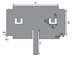
Figure 1 Single patch antenna element.
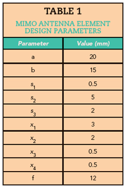
Figure 2a shows the beginning of the design evolution. In this circuit, a conventional rectangular patch antenna measuring 26 mm × 20 mm with an inset feed is designed. A single U-shaped slot is introduced, as shown in Figure 2b, and then a second slot is added in Figure 2c. These improve the element’s match to 50 Ω. Subsequently, the first notches (χ1, χ2) and the second notches (χ3, χ4) are introduced in Figure 2d to achieve the desired frequency of 3.5 GHz.
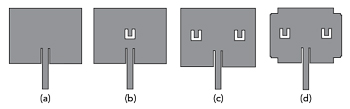
Figure 2 SN MIMO antenna element design evolution: Antenna 1 (a), Antenna 2 (b), Antenna 3 (c) and Antenna 4 (d).
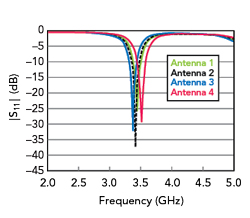
Figure 3 SN MIMO antenna element |S11| comparison.
Figure 3 shows the simulated |S11| of the four antennas. |S11| of the inset feed antenna, shown in Figure 2a, is -25.93 dB at 3.44 GHz. |S11| of the single U-shaped design of Figure 2b is -32.08 dB at 3.37 GHz. When two U-shaped slots are introduced in Figure 2c, the frequency shifts to 3.413 GHz with an |S11| of -34.05 dB. With the notches introduced in Figure 2d, the frequency shifts to 3.5 GHz with a fractional impedance bandwidth of 3.8 percent.
MIMO CONFIGURATION
2 × 2 SN MIMO Array
Figure 4a and Figure 4b illustrate two candidate configurations of the 2 × 2 SN MIMO microstrip patch antenna array, each with dimensions of 36 mm × 60 mm. The spacing between the two antennas is 10 mm. One of the key performance metrics is the ECC, which is remarkably low, measuring less than 0.02. Figure 4c shows a prototype of the side-by-side configuration of Figure 4a.
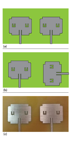
Figure 4 (a) Side-by-side 2 x 2 antenna configuration. (b) Orthogonal 2 x 2 antenna configuration. (c) Prototype side-by-side 2 x 2 antenna.
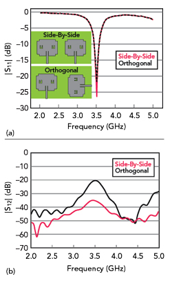
Figure 5 (a) |S11| for antenna element orientations. (b) |S12| for antenna element orientations.
Figure 5a compares the |S11| performance of the two candidate configurations and Figure 5b compares the |S12| performance of the two candidate configurations. The graphical results show that the side-by-side orientation outperforms the orthogonal configuration in terms of both reflection coefficient and isolation. Additionally, this is achieved without the need for additional structures or complex modifications. Therefore, the side-by-side orientation is chosen for the 4 × 4 antenna design.
4 x 4 MIMO Array
Building upon the 2 × 2 SN MIMO results, a 4 × 4 SN MIMO antenna is designed with the circuit configuration shown in Figure 6. Its dimensions are 68 mm × 68 mm with an inter-element spacing of 10 mm to provide good signal reception in a multipath environment. Simulated current distributions at 3.5 GHz are shown in Figure 7. The current is primarily focused around each patch, substantiating the antenna’s radiation in a specific frequency band. The current is also confined within each element without dissipation to other ports, supporting the observation of a high level of port-to-port isolation.
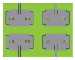
Figure 6 4 x 4 MIMO antenna.
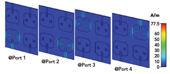
Figure 7 Current distribution of 4 x 4 SN MIMO antenna at 3.5 GHz with each port separately driven.