DESIGNING THE SIW DUAL-MODE DIPLEXER
The preceding analysis has shown that two kinds of SIW dual-mode resonators can be utilized to design the channel filters of the diplexer. Figure 5 shows the proposed structure of this circuit.

Figure 5 Proposed diplexer circuit structure.
Figure 6 shows the simulation results of the diplexer realized with two kinds of coupling circuits at a center frequency of 5 GHz and 5.25 GHz. Capacitive perturbation is adopted for the lower-channel filter at 5 GHz, while the magnetic coupling with the NRN is adopted for the upper-channel filter at 5.25 GHz. The dimension of the upper-channel filter is slightly smaller than that of the lower-channel filter. The relative bandwidths of the channel filters are 1.96 percent and 2.06 percent, respectively. The SIW dual-mode channel filters have high-frequency selectivity due to the transmission zeros on each side of the channel

Figure 6 Simulation results of the presented diplexer.
Zero-degree feeding-line technology is adopted in the diplexer to reduce the circuit size further and improve the isolation. The design of the T-junction connected to the two channel filters requires specifying only the ta and tb lengths, as shown in Figure 5. The length of the proposed microstrip line T-junction is much less than a conventional SIW T-junction. This allows the proposed microstrip line T-junction to be viewed as a zero-degree feeding line. This allows the proposed diplexer to be more compact with lower design complexity. The input and output feeding-line impedance is set to 50 Ohms. If the port1 GD(1,1) group delay meets the conditions of Equation 4, the channel filters can be designed independently, where CH1_GD(1, 1) and CH2_GD(1, 1) are the group delays of the two passbands. The circuit sizes are optimized to meet Equation 4, simplifying the diplexer and channel filter designs.

The design process of the diplexer can be summarized as follows:
- Determine the necessary quality factor and coupling coefficient of the two desired passbands based on the parameters of the circuit design
- Using these values, design the two channel filters of the diplexer and the T-junction
- Combine the channel filters with the microstrip T-junction into a diplexer
- Optimize the T-junction and the diplexer sizes for the desired results
RESULTS AND DISCUSSION
The proposed SIW dual-mode diplexer was optimized in ANSYS HFSS and verified by experiments. The optimized dimensions of the diplexer shown in Figure 5 are shown in Table 1.

Table 1 Diplexer circuit dimensions.

Figure 7 Simulated and measured loss and return loss.
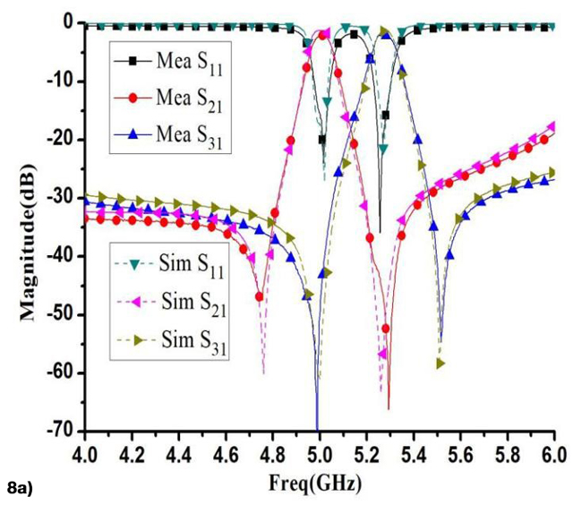
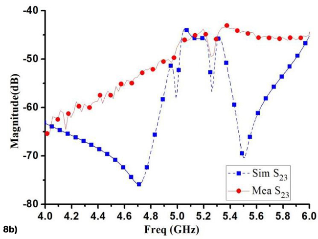
Figure 7 shows the SIW dual-mode diplexer fabricated using standard single-layer PCB fabrication processes. The substrate uses Taconic RF-35 with a permittivity of 3.5, a thickness of 0.508 mm and a loss tangent of 0.0018. The diplexer is 36 mm × 72 mm or λg × 2 λg, where λg is the guided wavelength at the center frequency of the first passband. Figure 8a shows the simulated and measured insertion loss and return loss results of the SIW dual-mode diplexer. Figure 8b shows the measured versus modeled isolation results for the diplexer. The measured center frequencies are 5 GHz and 5.25 GHz and the relative bandwidth of the two channels are 1.96 percent and 2.06 percent. Both channels are well matched, with the measured return loss greater than 20 dB. The measured insertion loss of the two channels are 2.01 dB and 2.13 dB, respectively and the measured isolation is greater than 45 dB in both channels. While there is good agreement between the simulated and measured results, errors can be attributed to the fabrication and measurement process and the losses of the SMA connectors.

Figure 8a Simulated and measured loss and return loss.

Figure 8b Simulated and measured isolation results.
Table 2 compares the proposed diplexers and reported results. Compared with the references, the diplexer described in this article is smaller, has higher isolation between the two channels and has lower insertion loss. In addition, two transmission zeros near the two sides of each passband have greatly improved the frequency selectivity of the diplexer presented in this article.
Table 2.
Table 2 Performance comparison.
CONCLUSION
This article has described a compact, high-isolation SIW diplexer with high-frequency selectivity. The electromagnetic perturbation and magnetic coupling between the NRN and the even mode have introduced two transmission zeros on both sides of each passband. This technique improves the frequency selectivity of each channel of the duplexer and the isolation between the two channels. The diplexer has been designed, fabricated and measured with good agreement between the simulated and measured results.
ACKNOWLEDGEMENT
This work was partly supported by the National Natural Science Foundation of China (Grant No: 62171097).
REFERENCES
- ZHANG, Sheng, et al. Miniaturized Bandpass Filter Using Quarter SIW Resonator With Elliptic Defected Structure. Channels, 2017, 4: 5G.
- E. Massoni, N. Delmonte, G. Macchiarella, L. Perregrini and M. Bozzi, "Half-mode SIW Filters with Resonant Couplings Implementing Transmission Zeros," 2018 IEEE/MTT-S International Microwave Symposium - IMS, Philadelphia, PA, USA, 2018, pp. 701-703.
- K. Benderradji, I. Messaoudene, R. Rebbah, B. Hammache and M. Belazzoug, "Design of Ka-Band Planar Pass-band Filter of Fifth Order Based on SIW Technology," 2022 Workshop on Microwave Theory and Techniques in Wireless Communications (MTTW), Riga, Latvia, 2022, pp. 72-76.
- K. Song, Y. Fan X. Zhou, “X-band broadband substrate integrated rectangular waveguide power divider,” Electronics Letters, 2008, 44(3): 211-213.
- K. Song, Y. Fan, Y. Zhang, “Eight-way substrate integrated waveguide power divider with low insertion loss,” IEEE Transactions on Microwave Theory and Techniques, vol. 56, no. 6, pp. 1473-1477, 2008.
- J. Chen, W. Hong, Z. Hao, H. Li, K. Wu, “Development of a low cost microwave mixer using a broad-band substrate integrated waveguide (SIW) coupler,” IEEE Microwave and Wireless Components Letters, 2006, 16(2): 84-86.
- Ning Zhang, Qing Liu and Jin-Kui Yan, "Directional couplers based on substrate integrated waveguide," 2017 8th International Conference on Mechanical and Intelligent Manufacturing Technologies (ICMIMT), Cape Town, 2017, pp. 183-187.
- F. Cheng, X. Lin, K. Song, “Compact Diplexer With High Isolation Using the Dual-Mode Substrate Integrated Waveguide Resonator,” IEEE Microwave and Wireless Components Letters, vol. 23, no. 9, pp.459-461, 2013.
- D. Bukuru, K. Song, “Compact Wide-stopband Planar Diplexer Based on Rectangular Dual Spiral Resonator,” Microwave and Optical Technology Letters, vol. 57, no. 1, pp. 174-178, 2015.
- N. H. Baba, M. T. Ali, Aziati H. Awang, H. M. Hizan, “First order diplexer using SIW-based circular cavity resonator,” 2015 IEEE International RF and Microwave Conference, 14-16, Dec. 2015.
- Kang Zhou, Chun-Xia Zhou, Wen Wu, “Compact SIW Diplexer with Flexibly Allocated Bandwidths using Common Dual-Mode Cavities,” IEEE Microwave and Wireless Components Letters, Vol. 28, no. 4, April 2018.
- A. Khan, M. Mandal, “Compact Self-Diplexing Antenna Using Dual-Mode SIW Square Cavity,” IEEE Antennas and Wireless Propagation Letters, vol. 18, no. 2, Feb. 2019.
- Z. Su, B. Xu, S. Zheng, H. Liu, Y. Long, “High-isolation and Wide-stopband SIW Diplexer using Mixed Electric and Magnetic Coupling,” IEEE Transactions on Circuits and Systems II: Express Briefs, vol. 67, no. 1, pp. 32–36, 2020
- P. Chu, W. Hong, M. Tuo, K. Zheng, W. Yang, F. Xu, K. Wu, “Dual-Mode Substrate Integrated Waveguide Filter With Flexible Response,” IEEE Transactions on Microwave Theory and Techniques, vol. 65, no. 3, Mar. 2017.
- S. Sirci, J. D. Martinez, J. Vague, V. E. Boria, “Substrate integrated waveguide diplexer based on circular triplet combline filters,” IEEE Microwave and Wireless Components Letters, vol. 25, no. 7, pp. 430–432, Jul. 2015.
- Q. Duan, K. Song, “Compact Wide-Stopband Diplexer using dual mode resonators,” Electronics Letters, vol. 51, no. 14, pp. 1085-1086,2015.
- Han L, Wu K, Chen X P, et al. Packaged Microstrip Line Diplexer Using SIRs[J]. Microwave Journal, 2011.
- Xu H X, Wang G M, Liang J G, et al. A Compact Microstrip Diplexer Using Composite Right-/Left-Handed Transmission Line with Enhanced Harmonic Suppression [J]. Microwave Journal, 2011, 54(11).
- Singh K, Ngachenchaiah K, Bhatnagar D, et al. Notch Implemented Dual Behavior Resonator Filter and Diplexer at Ku-band [J]. Microwave Journal, 2010, 53(4).
- H. -S. Peng and Y. -C. Chiang, "Microstrip Diplexer Constructed With New Types of Dual-Mode Ring Filters," in IEEE Microwave and Wireless Components Letters, vol. 25, no. 1, pp. 7-9, Jan. 2015
- X. Guan, W. Liu, B. Ren, M. Xu, X. Zhang and Z. Ma, "Synthesized Microstrip Diplexer with Coplanar Waveguide Feeding Based on Composite Resonators," 2020 International Conference on Microwave and Millimeter Wave Technology (ICMMT), Shanghai, China, 2020, pp. 1-3.
- Grman M. Frequency Agile Diplexer[J]. Microwave Journal, 2015, 58(10).
- H. Oraizi, E. Bidaki, “Optimum design of a miniaturized multilayer SIW diplexer using orthogonal-mode resonator,” 7th International Symposium on Telecommunications, 9-11 Sept. 2014.
- W. Shen, X. Sun, W. Yin, J. Mao, Q. Wei, “A novel single-cavity dual-mode substrate integrated waveguide filter with non-resonating node,” IEEE Microwave and Wireless Components Letters, 2009, 19(6): 386-388.

