

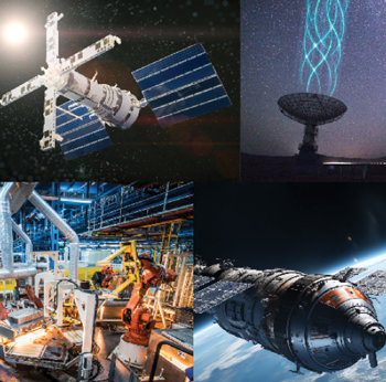
Figure 1 Applications that will focus on D-Band frequencies.
The call for more D-Band (110 to 170 GHz) applications has gone out. With the ability to transmit 100 Gbps, D-Band will answer this call by unlocking several technologies across a wide range of industries. Wireless communication is often the focal point, but other commercial applications include high-precision sensing, radio astronomy, IoT, automation and airport security detectors. For the military, D-Band will open the door to applications like the next generation of inter-satellite links, imaging radars and stand-off detection. Figure 1 shows renditions and images of some of the applications that will benefit from the capabilities that D-Band will enable.
However, as research and development teams attempt to deliver on the much-anticipated move into D-Band, they are running into the common problem of signal reflections caused by mismatches. These undesirable reflections can attenuate power output, distort the digital information on the carrier and in extreme cases, damage internal components. To offset the issue of mismatches at lower microwave frequencies, engineers rely on Faraday rotation isolators. Unfortunately, the performance of traditional isolators at mmWave frequencies still lags what engineers have become accustomed to at lower frequencies. At higher D-Band frequencies, traditional isolators often struggle to deliver the same results. Above 110 GHz, you enter uncharted territory. Connectivity has become particularly important and cables do not work very well at these frequencies. As operating frequencies climb higher, most of the connections are made in waveguides.
SUPPRESSING SIGNAL REFLECTIONS
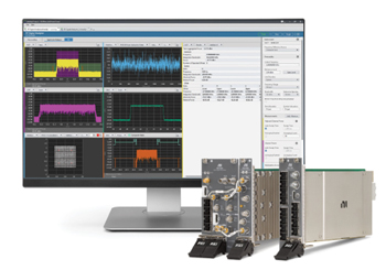
Figure 2 NI open standard PXI test system.
Until recently, the availability of test and measurement equipment at D-Band frequencies has been limited. There are few standards and little to no traceability to the National Institute of Standards and Technology (NIST). If an engineer sets up their equipment to test or measure at these frequencies and something goes wrong, they spend most of their time trying to figure out whether the issue is their test equipment or the device that they are evaluating.
Since the industry is in the early days of development of D-Band applications, the deployment profile will rely heavily on the availability of test equipment. Without equipment that can reliably enable efficient and accurate measurement, comprehensive research, testing and validation is more difficult and time-consuming. Figure 2 shows controllers for an NI PXI test system, along with the associated software for a 6G sub-THz reference architecture. As NI was developing this capability, the challenge of reflected waves in the waveguides became apparent. As frequencies are swept, the phase changes and this results in nulls, dips and degraded performance. Early in the design process, NI realized that the frequency-dependent phase change, coupled with bad mismatches in the waveguide system was causing substantial frequency ripples in the measurements.
These effects are not unique to D-Band. To resolve these challenges at microwave frequencies, engineers simply insert an isolator between components to absorb the reflected signal. However, as you move up the electromagnetic spectrum, shorter wavelengths require smaller constituent parts. At mmWave frequencies, the distance between components is often much larger than a wavelength and the parts are so small that even the smallest misalignment can significantly degrade performance.
ADVANCES IN MMWave ISOLATOR DESIGN
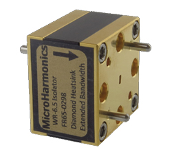
Figure 3 Micro Harmonics WR-6.5 isolator.
As demand for D-Band systems increases, so does the number of available isolator options. Unfortunately, the performance of the available isolators still lags what engineers have become accustomed to at lower frequencies. Looking to solve this issue and deliver reliable test, measurement and prototyping equipment for D-Band led NI to THz-enabled isolators designed for NASA. After evaluating the isolators on the market, they determined that offerings from Micro Harmonics were the most appropriate solution for their challenges. Figure 3 shows an isolator from Micro Harmonics that operates to 330 GHz.
Micro Harmonics Corporation is a Virginia-based manufacturer specializing in the design of mmWave components. Under a NASA contract, Micro Harmonics developed a new design technique that improves performance, allowing the isolator to operate well into THz frequencies. The traditional method to manufacture an isolator has been to use ferrites that are substantially longer than required and then tune the magnetic bias field to achieve optimal performance. This delivers good isolation but at a much higher insertion loss.
Based on a design for NASA requirements, Micro Harmonics minimized the insertion loss of the isolator by reducing the ferrite length by as much as possible. The design developed for NASA saturates the ferrite with a strong magnetic bias field, which results in the shortest possible length of ferrite to achieve the ideal 45 degrees of rotation. This technique lowers the insertion loss to less than 1 dB in the 75 to 110 GHz frequency range and only 2 dB in the 220 to 330 GHz frequency range. The S-parameter performance of this isolator over D-Band is shown in Figure 4.
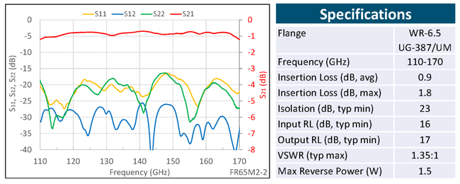
Figure 4 D-Band isolator test data.
This technique of saturating the ferrite with a strong magnetic bias field to shorten the ferrite has resulted in a portfolio of isolators that operate in waveguide bands from 50 to 400 GHz. The loss, in terms of transmission percentage, is shown in Figure 5. Also plotted in Figure 5 are results from legacy isolators using conventional design techniques. The chart shows the dramatic improvement in insertion loss values, along with the ability to manufacture an isolator that operates up to 400 GHz.
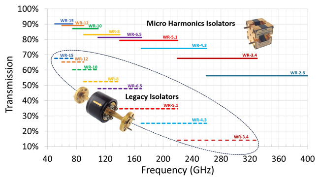
Figure 5 Insertion loss comparison for Micro Harmonics isolators versus traditional style isolators.
To confirm that the improved isolator performance improved the test system performance, NI measured their systems before and after inserting the isolator. The result was a noticeable improvement in the ripple and a reduction in the mismatch reflections, confirming the premise that the ripples were caused by reflected waves from mismatches. Using this new isolator design allowed NI to announce a 6G sub-THz reference architecture that provides calibrated measurements with up to four GHz of modulation bandwidth. This development greatly enhances the ability to receive and transmit at D-Band. It also enables the use of software-defined radio techniques to prototype and make measurements that are traceable to a power meter. These isolators also offer the added benefit of covering the entire D-Band frequency range with their specified performance. They are housed in a small cube that fits directly onto a flush surface without a rear-accessible flange, eliminating the need for extra waveguide sections.
ENABLING D-BAND DEVELOPMENT
The insatiable demand for data bandwidth, especially for communications and the existing spectrum available in the D-Band frequency range has companies charging ahead at light speed. To tap into the allure of the frequency range, the FCC recently allowed experimental licenses in D-Band and up to 220 GHz to facilitate companies to develop new broadband communication methods that will make use of the wide channel bandwidths available at those frequencies. The result has been an increase in sub-THz communication research and development. Companies are designing next-generation chipsets, radio links and protocols and solving the frequency-dependent ripple issues is enabling new mmWave test and measurement equipment as well as software-defined radios. Having reliable, accurate test equipment is accelerating prototyping and next-generation wireless innovation in D-Band and other sub-THz frequency bands.