Materials, such as ferrites or liquid crystals, enable dielectric substrate RA tuning by adjusting relative permittivity and permeability to change antenna resonant frequencies but high voltages are needed to modify dielectric substrate properties.
Each RA technique has benefits and drawbacks; however, the electrical techniques are most suitable. Reconfigurability is accomplished using a PIN diode, a varactor diode or RF MEMS. These technologies are reliable, highly efficient and easily integrated with the microwave circuit.
A comparison of leading switch techniques is shown in Table II with the merits and demerits of all techniques listed in Table III.
TABLE II SWITCH COMPARISON

TABLE III RA TECHNIQUES MERITS AND DEMERITS

When efficiency and compactness are the most important considerations, electrically reconfigurable antennas provide the best solution. However, the lifetime and power handling capacity of switches are important factors. Figure 7 shows the PIN diode's equivalent circuit in both the ON and OFF modes. A simple RL series circuit with an inductor L(nH) and a low-value resistor R (Ω) is created when the PIN diode is ON. The circuit becomes RLC when the PIN diode is in the OFF state. A high-value resistor R (KΩ) and a capacitor C (pF) are connected in parallel to an inductor L(nH) series. The ground surface, patch surface and antenna resonant frequency surface current distribution change with the switch configuration.11, 12

Figure 7 PIN diode equivalent circuit: on state (a), off state (b).
CRRFEH DESIGN
The CR-RFEH circuit design process is shown in Figure 8. The design flow is as follows:
Step-1. Design a UWB DRA sensing antenna (see Figure 9).
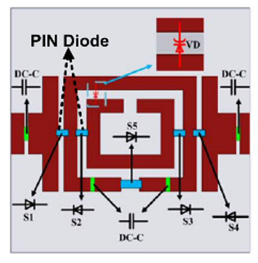
Step-2. Design a communication antenna with reconfigurability (see Figure 10 for the design of the reconfigurable filter). PIN and varactor diodes are used to provide the reconfigurability function.
Step-3. Design an RFEH antenna (see Figure 11).
Step-4. Design a rectifier circuit for the RFEH rectifier-antenna (rectenna) system to convert the RF to DC. (see Figure 11)
Step-5. Select the impedance matching network (IMN), voltage multiplier and storage unit. (see Figure 11)
Step-6. Combine all RFEH elements and design the CRRFEH circuit.

Figure 8 RFEH design flow.

Figure 9 Ultra-wideband DRA antenna design evolution: three configurations (a), |S11| (b).2 (a=42; b=40; i=14; j=11.5; e=9; c=4.5; d=20.42; f=17; g=11 (all dimensions are in mm)


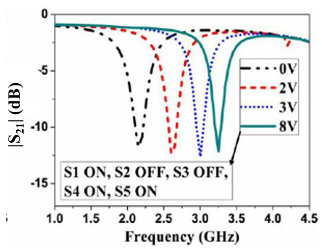
Figure 10 RA filter: design (a) and S-parameters (b)(c).1
Figure 9 shows the design progression of a UWB DRA. It is connected to a multifunctional reconfigurable filter (see Figure 10a) that operates in three modes: all pass (APF), bandpass (BPF) and band reject (BRF). When PIN diodes S1 through S4 are “ON” and S5 is off, it is an APF with the corresponding |S11| in Figure 10b. In this case, it works as a sensing antenna in conjunction with the UWB DRA. When all PIN diodes are “OFF,” it is a varactor-tuned BPF. In this case, it works as a communicating antenna for interweave CR with the corresponding |S11| in Figure 10b. When S1, S4, and S5 are “ON” and S2 and S3 are “OFF,” it operates as a varactor-tuned BRF. In this case, it works as an underlay CR with the corresponding |S21| in Figure 10c.

Figure 11 RFEH block diagram.
The basic building blocks of the rectenna system in Figure 11 are an antenna, RF input filter, IMN, rectifier circuit and a DC filter. The main function of an antenna is to sense and receive the RF signal from power sources at different frequencies. These radio signals are transferred to the rectifier through an IMN to maximize power transfer. The rectifier circuit converts the RF signal to DC. Through the DC filter, it powers the load, which can be a storage device. The RF filter, also called a pre-rectifier filter, is used to suppress harmonics produced by the nonlinear rectifier.
If the antenna receives more power, the power to the rectifier circuit is greater as is the power delivered to the load. The performance of a rectenna system depends on a rectifier's power conversion efficiency (PCE) and the ability of the antenna to harvest RF energy. The ratio of the output DC to the input RF power is the rectifier PCE.
RFEH ZONES
The energy harvesting, interference and transmission zones associated with a primary base station (PBS) are shown in Figure 12. SUs receive RF energy from the PBS, PUs, secondary base station (SBSs) and other SUs. In the transmission zone, PUs can communicate with the PBS. SUs in the transmission zone use the RF signal to transmit and transfer energy. In the energy-harvesting zone, SUs can harvest energy directly from the PBS because of the strong primary RF signal. If the PBS or PUs occupy the spectrum in the interference zone, the SU cannot transmit.11,12

Figure 12 RFEH zones.
A comparison between various 2-port and 4-port microstrip antennas and DRAs with CR is shown in Table IV.2 From Table IV, it is clear that the DRA with CR provides greater sensing range, tuning bandwidth and gain compared with other approaches.
TABLE IV COMPARISON OF CR TECHNIQUES WITH EXPERIMENTAL DATA

CHALLENGES
The design of a UWB communication antenna and a rectenna system for CRRFEH is challenging. In CR, the most challenging task is to design a UWB antenna with a multifunctional switchable filter operating as an APF, BPF and BRF for sensing, interweave and underlay communication.
The most important parameter for an RFEH (or rectenna) system is PCE.4, 5 Obtaining high PCE is challenging. One approach way to realizing high PCE is through optimizing the IMN. The IMN is designed in such a way as to collect the maximum power and deliver this power to the rectifying circuit. High PCE is also obtained by suppressing harmonics generated by nonlinear diode characteristics.
Various antenna designs are used to maximize receiving capacity. PCE is affected if the antenna receives very low RF power due to a polarization mismatch between the transmitter and receiver. Dual-band or broadband antennas capture more RF power than single-band antennas. Antenna arrays increase the antenna aperture size for higher antenna gain to increase received power.
In RFEH, the antenna should be light in weight, low cost, high gain, small and easily integrated. Schottky diodes are important components because they efficiently convert RF to DC. Higher PCE is obtained when all the elements of the rectenna system are executed properly.4-7
CONCLUSION
An overview of RFEH with CR in wireless communication systems provides a comparison of different switches and CR techniques. CR with a DRA antenna provides improved performance. The environment is filled with numerous harmless RF energy sources that can be emitted from any object. But in the surrounding environment, RF energy has a very low power density. Designing RFEH systems presents the major problem of maximizing PCE with low input power. An energy-harvesting CR offers the potential benefits of a continuous lifetime without requiring external power cables or the regular recharging of batteries, and it has the capacity to take advantage of an underutilized spectrum.
References
- S. R. Thummaluru, M. Ameen and R. K. Chaudhary, “Four-Port MIMO Cognitive Radio System for Midband 5G Applications,” IEEE Transactions on Antennas and Propagation, Vol. 67, No. 8, August 2019, pp. 5634-5645.
- K. Tyagi, A. K. Dwivedi, S. K. Singh, P. Ranjan and A. Sharma, “Four Port Dielectric Resonator Based MIMO Antenna Design for Cognitive Radio Applications,” IEEE Transactions on Circuits and Systems II: Express Briefs, Vol. 70, No. 6, June 2023, pp. 1936-1940.
- Y. Tawk, J. Costantine and C. G. Christodoulou. “Cognitive-Radio and Antenna Functionalities: A Tutorial [Wireless Corner],” IEEE Antennas and Propagation Magazine, Vol. 56, No. 1, February 2014, pp. 231-243.
- X. Lu, P. Wang, D. Niyato and E. Hossain, “Dynamic Spectrum Access in Cognitive Radio Networks with RF Energy Harvesting,” IEEE Wireless Communications, Vol. 21, No. 3, June 2014, pp. 102-110.
- L. Mohjazi, M. Dianati, G. K. Karagiannidis, S. Muhaida and M. Al-Qutayri, “RF-Powered Cognitive Radio Networks: Technical Challenges and Limitations,” IEEE Communications Magazine, Vol. 53, No. 4, April 2015, pp. 94-100.
- M. A. Halimi, T. Khan, Nasimuddin, A. A. Kishk and Y. M. M. Antar “Rectifier Circuits for RF Energy Harvesting and Wireless Power Transfer Applications: A Comprehensive Review Based on Operating Conditions,” IEEE Microwave Magazine, Vol. 24, No. 1, January 2023, pp. 46-61.
- P. Sharma and A. K. Singh, “A Survey on RF Energy Harvesting Techniques for Lifetime Enhancement of Wireless Sensor Networks,” Sustainable Computing: Informatics and Systems, Vol. 37, January 2023.
- R. K. Mongia and P. Bhartia, “Dielectric Resonator Antennas - A Review and General Design Relations for Resonant frequency and Bandwidth,” International Journal of Microwave and Millimeter-Wave Computer-Aided Engineering, Vol. 4, No. 3, July 1994, pp. 230-247.
- P. Ranjan and R. K. Gangwar, “Probe Feed Half Split Cylindrical Dielectric Resonator Antenna for Wideband Application,” AEU International Journal of Electronics and Communications, Vl. 69, No. 11, November 2015, pp 1709-1714.
- A. Sharma, G. Das, P. Ranjan, N. K. Sahu, and R. K. Gangwar, “Novel Feeding Mechanism to Stimulate Triple Radiating Modes in Cylindrical Dielectric Resonator Antenna,” IEEE Access, Vol. 4, November 2016, pp 9987-9992.
- H. C. Mohanta, A. Z. Kouzani and S. K. Mandal, “Reconfigurable Antennas and their Applications” Universal journal of Electrical and Electronics Engineering,” Vol. 6, No. 4, October 2019, pp. 239-258.
- N. O. Parchin, H. J. Basherlou, Y. I. Al-Yasir, A. M. Abdulkhaleq and R. A. Abd-Alhameed, “Reconfigurable Antennas: Switching Techniques - A Survey,” Electronics, Vol. 9, No. 2, February 2020.

