

In recent years, we have observed a rapid evolution in the field of satellite communications (satcom). The decreasing cost of accessing space has led to the emergence of new satellite constellations, particularly non-geostationary systems, designed to deliver high speed data connectivity worldwide. In-flight connectivity is becoming increasingly prevalent as coverage areas expand and data rates continue to improve with geostationary (GEO) satellites and planned low earth orbit (LEO) constellations. This shift has necessitated fundamental changes to satellite terminal equipment, as the pointing vector to and from the satellite is no longer fixed. Tracking antennas are a crucial technology for implementing these advancements, ensuring a continuous line of sight to the satellite when the satellite and the terminal are in motion relative to each other.
For some, antennas have traditionally been the least understood part of the communication system. The process in which microwave energy is radiated into free space and shaped in a specific radiation pattern seemed like the ultimate “black magic.” This article aims to demystify the operation of electronically steered antennas (ESAs) for those tasked with integrating these advanced antennas into their satcom solutions. Anticipating the challenges with antenna technologies, this article provides a simple yet comprehensive explanation of how ESAs work, while delving into their inherent characteristics. It also highlights key considerations in the design of satcom solutions that feature these antennas.
WHAT IS AN ESA?
In simple terms, an ESA is an antenna that can electronically move its beam pattern in both azimuth and elevation planes without moving physical parts. While ESAs have been in existence for several decades, their prohibitive cost made them most suitable for defense applications. However, the emergence of low-cost RFIC technology, coupled with advanced simulation capabilities, has made it possible to lower the cost of ESAs and extend their utility to commercial applications.
WHY USE AN ESA?
Antenna beam steering has been a mechanical process for many years in radar applications and earth stations for LEO observation satellites. The first commercial satellite in-flight connectivity system, Connexion by Boeing, used a mechanically steered tracking antenna in 2003.1 In addition to improving reliability by eliminating moving parts, ESA technology provides several fundamental advantages over mechanically steered antennas. The ability to independently track more than one satellite and to switch between satellites in less than one millisecond are just two of these advantages. These and other characteristics are not possible with mechanically steerable antennas and are critical to unlocking the full potential of newer LEO constellations.
FUNDAMENTALS OF ESA
This section explains antenna and phased array operating principles. This understanding is essential to ESA functions, capabilities and limitations.
Antenna Arrays and Phased Arrays
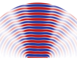
Figure 1 Radiation pattern of a line array.2
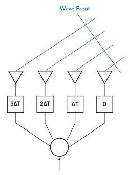
Figure 2 Electronic beam steering using time delay.
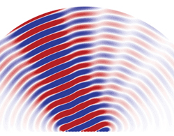
Figure 3 Steered radiation pattern with time delay.3
An antenna array consists of several radiating elements, arranged in a certain configuration to create a desired radiation pattern. A phased array is an antenna array that can electronically steer its radiation pattern by changing the phase of the signal that feeds each element of the array. In a simple antenna array, two identical isotropic radiating elements are placed with a half-wavelength separation from each other and fed with identical power and phase. The radiated power from these two elements will be the sum of the power of each element in the direction perpendicular to the plane of the elements, called boresight and zero in the direction parallel to the plane. The beam created by these two elements is narrower than that of the individual isotropic radiators.
Adding more elements to the array increases the equivalent aperture size of the array and the beam gets narrower in the plane perpendicular to the row of elements. In antenna terminology, the gain of the antenna increases, or more accurately, the directivity that increases. Figure 1 shows the radiation pattern of a line array. The dark area along the centerline of the radiation pattern is the main lobe and the lighter areas are the side lobes.
This pattern is the result of the constructive and destructive interference between these elements. The radiation pattern of this simple array is the product of the radiation pattern of the individual element and the array factor. The array factor describes the effect of placing multiple radiating elements at a certain configuration and spacing.
Electronic Beam Steering
Figure 2 shows the effect on the waveform of adding a time delay to the input of each element in an array. The time delay matches the time difference of the wavefront emitted from each element. The applied delay causes the four signals to combine in phase in a specific spatial direction that is related to the time delay magnitude. Figure 3 shows the steered radiation pattern of the array shown in Figure 1.
In many practical implementations of phased array antennas, time delay is implemented using phase shifters. However, time delay and phase shift are not equivalent. This difference will be discussed, along with how this affects beam squint later in the article. The analysis to this point has assumed a one-dimensional (1D) array for simplicity. ESAs used for satcom are two-dimensional (2D) arrays that create a pencil-like pattern. These next sections discuss some of the features and challenges of 2D ESA arrays.
Beam Shaping, Forming and Sidelobe Level Control
Controlling the phase of the signal to each array element steers the radiation pattern in space. If all array elements are fed with the same power level, it creates a uniform aperture illumination. Uniform illumination yields maximum aperture efficiency, however, feeding different array elements with different power levels can lower sidelobe levels and create nulls in directions of interference. Depending on the specifics of the implementation, this can be done dynamically to reduce interference, as an example.
A useful feature of phased arrays is that they can be used to create and steer multiple beams simultaneously and independently of each other. A set of complex amplitude and phase weighting functions can be fed to each element of the array to shape the radiation patterns and steer it to the desired spatial location. Since the array elements are linear devices, different sets of complex weights can be applied simultaneously to the array to create multiple beams, by the principle of superposition.
While a phased array antenna can rapidly switch pointing between satellites, this capability comes at the cost of reducing the satellite duty cycle, which translates to reduced capacity. Multiple simultaneous beams allow communication with multiple satellites at the same time. However, this capability results in a more complex antenna implementation.
The Effect of Scan Angle on Antenna Performance
Since phased array antennas steer beams without physically moving the array, the line of sight between the antenna and the satellite is often not normal to the plane of the array. This means that the effective area of the antenna is reduced, as only a projection of the full area is exposed to the satellite. This creates a scan loss, reducing the overall gain of the antenna. This is a fundamental difference between phased array antennas and other antenna designs.
This loss is approximately 10 log (cos (θ)), with θ being the angle between a line normal to the array’s plane and the line of sight to the satellite. At θ=60 degrees, for example, the scan loss is 3 dB. Depending on the specific design of the array, scan losses tend to be slightly higher than 10 log (cos (θ)), especially at higher values of θ.
Time Delay Versus Phase Shift
As shown in Figure 2, steering an antenna beam depends on delaying the wavefront between elements. This delay is commonly implemented with phase shifters. However, a phase shifter creates a frequency-dependent time delay, making this approach most useful for a narrow band of frequencies. Newer satcom systems use wideband waveforms, meaning that the time delay will not be constant for a fixed phase shift. As a result, the beam changes direction as a function of frequency. This change in the beam’s pointing vector with frequency is called beam squint. Beam squint is also a function of the scan angle θ and is more pronounced at higher values of θ.
Grating Lobes
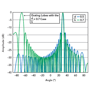
Figure 4 Normalized array factor of a 32-element linear array.1
The concept of grating lobes is derived from a mathematical description of a phased array antenna and is beyond the scope of this article. However, an example helps with the concept. Figure 4 shows the array factor of a 32-element array with element spacing of 0.5λ and 0.7λ. Element spacing of 0.7λ yields a narrower main beam and a tighter sidelobe pattern. This improvement results from a larger aperture area, where the same number of elements have more spacing between them. However, this configuration also produces another full gain beam at -70 degrees. This is a grating lobe and this beam may transmit power to or receive power from an undesired direction. This will interfere with other satellites or terminals and it may pick up undesired signals and noise. However, this phenomenon does not necessarily mean that element spacing must always be kept below a half-wavelength.
ESA-BASED SATCOM SOLUTIONS
There are several important design considerations when integrating an ESA into a satcom solution. This section and the article concentrates on active flat arrays, which have gained popularity thanks to their design flexibility, low-profile and cost-effectiveness. Active flat arrays for two-way satcom typically feature two separate apertures; one for receive and one for transmit. The dual aperture configuration significantly simplifies the design of the antenna.
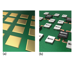
Figure 5 (a) Flat panel array antenna patches and (b) flat panel array ICs on the back of the antenna PCB.5
Each flat array aperture is built with unit cells and each unit cell contains several radiating elements and an RFIC. The unit cell is tiled in two dimensions to create the desired aperture area. This structure is easy to implement on a single printed circuit board (PCB) and the result is a very compact, low-profile antenna. In this design, printed radiating elements are on top of the PCB, as shown in Figure 5a, and RFICs are placed on the back, as shown in Figure 5b. Each of the receive antenna elements feeds a low noise amplifier and each transmit element is driven by a power amplifier (PA). This antenna architecture is different from traditional satcom antenna designs and has several aspects that should be carefully evaluated.
Unlike traditional dish antennas, ESAs do not have standard sizes. ESA-based terminals are usually customized to the application with aperture size as the primary customization feature. Separate receive and transmitted apertures provide a degree of freedom, allowing the satellite link designer to optimize aperture size based on link performance in each direction. Since the aperture is built from multiple unit cells, aperture size directly impacts cost, power consumption and heat dissipation.
As described earlier, the effective aperture area decreases as the scan angle increases. This scan loss, based on the look angle to the satellite should be factored into the link budget design. For example, the elevation angle to a GEO satellite from an antenna onboard a commercial aircraft crossing the Atlantic Ocean at latitudes between 40 degrees and 50 degrees is between 40 degrees and 30 degrees. This is a simplified result since the orbital location of the satellite also affects the elevation angle. However, the result is a scan angle of 50 degrees to 60 degrees from boresight. The scan loss at a 60-degree scan angle is 3 dB, which is significant and applies to both receive and transmit apertures. The analysis indicates that the minimum antenna performance should be specified at the maximum anticipated scan angle.
The receive aperture size will be determined by the antenna gain to noise temperature ratio (G/T) required to satisfy the downlink performance requirements. This ratio is directly proportional to the aperture area. Determining the transmit aperture size is more complicated. In a traditional terminal design, the effective isotropic radiated power (EIRP) is determined by two independent quantities: antenna gain and block up-converter or HPA power. In an ESA, these two quantities are both a function of aperture size. Antenna gain is directly proportional to the aperture area. Transmit power is the sum of all contributions of power from each radiating element and the antenna gain and transmit power increase with increasing aperture area.
Antenna gain is proportional to 10log (N), where N is the number of elements. Multiplying the number of receive aperture elements by two increases the G/T by 3 dB/°K. Multiplying the number of transmit aperture elements by two increases the EIRP by 6 dB, as both gain and power double.
The aperture size of the ESA must satisfy several requirements, including link budget and adjacent satellite interference requirements. The antenna pattern must be narrow enough to meet the interference performance. If the aperture size must increase beyond what the link budget requires, power throttling may be considered.
Since an ESA contains two apertures, it has a larger footprint. Depending on the implementation technology, this may result in a lower profile. The mechanical configuration shown in Figure 5a and Figure 5b creates heat dissipation challenges, since these RFICs mount on the bottom side of the antenna PCB, which is not optimal for heat removal. Proper heat analysis and cooling methods must be considered to remove the heat from that area. In certain applications, like aircraft fuselage-mounted antennas, the operating time of the antenna on the tarmac may be limited without the cooling provided by airflow during flight.
To an extent, any ESA is customized by replicating a predesigned antenna unit-cell to create the required aperture size. The mechanical design, RF channel gain, frequency conversion and IF interface with the modem may also be adapted for a specific application. However, designing a user terminal as part of an integrated satcom system allows the terminal ESA to be optimized and simplified by accommodating the characteristics of the satellite constellation and air interface.
To this point, the antenna architecture has assumed a separate receive and a transmit aperture. A notable exception to this architecture is the Starlink terminal antenna. This architecture features a single transmit and receive aperture. The Starlink system is a proprietary closed system, without much publicly available information. The available information suggests that the Starlink air interface is half-duplex, eliminating the need for isolation between receive and transmit signal paths. This simplifies the unit cell design and allows the same array element to be used for non-simultaneous receive and transmit.
Another characteristic of this terminal is that during installation the antenna panel is mechanically tilted towards the sky at a certain elevation angle. This hints that the antenna is not required for large scan angles. This is supported by an angular separation between satellites in each orbital plane of about 20 degrees and an angular separation between orbits of only 5 degrees. These small angular separations allow for a limited scan range, which means lower scan loss. This means antenna performance barely degrades as it scans. This also allows element spacing greater than a half-wavelength and this means fewer unit cells to achieve the required gain, no grating lobes, reduced power consumption and lower cost.
In the earlier analysis, the ability to generate multiple independent beams was touted as an ESA advantage. When implementing an ESA for multi-beam applications, close collaboration with an antenna vendor becomes important. This collaboration is necessary for both sides to understand the specific antenna architecture and the multi-beam implementation. The details of multi-beam operation can easily affect both the cost and power consumption of the antenna.
Implementing beamforming techniques to create multiple beams allows for simultaneous communication with multiple satellites. Effective beamforming enables the formation of multiple beams, with each beam fully utilizing the entire antenna aperture, thereby maintaining consistent antenna gain across all beams. This is distinct from creating multiple beams by using only sections of the array, which would result in each beam having a reduced gain.
For multi-beam transmit antennas implemented with unit cells incorporating a PA, the EIRP per signal is reduced similarly. The formula for calculating EIRP is shown in Equation 1:
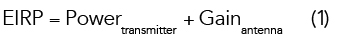
where all values are in dB and dBm.
While antenna gain remains the same for multi-beam operation, the PA output is finite and splits between two or more signals, assuming a single PA. In addition, the EIRP reduction might be more than 10log (number of beams) if the operating point of the PA must be backed off further to meet spectral regrowth requirements.
CONCLUSION
Recent advancements in phased array antenna and RFIC design are enabling more affordable ESA technology for commercial applications. ESAs can revolutionize satcom with their ability to electronically steer beams to provide connectivity to mobile platforms. This article has presented the fundamentals of ESAs, explaining the principles of phased array antennas and beamforming, as well as the advantages of flat phased arrays compared to traditional antenna designs. ESAs allow multiple satellites to be tracked simultaneously, which contributes to the development of the industry. These developments are enabling more commercial and defense space applications, but as this article has described, some challenges remain when designing and implementing ESA-based satcom solutions.
References
- “Connexion by Boeing,” Wikipedia, Web: https://en.wikipedia.org/wiki/Connexion_by_Boeing.
- “Phased array,” Wikipedia, Web: https://en.wikipedia.org/wiki/Phased_array.
- P. Delos, B. Broughton and J. Kraft, “Phased Array Antenna Patterns—Part 2: Grating Lobes and Beam Squint,” ADI Analog Dialogue, Vol. 54, June 2020, Web: https://www.analog.com/en/analog-dialogue/articles/phased-array-antenna-patterns-part2.html.
- “Phased array beamforming ICs simplify antenna design,” eeNews Wireless, Web: https://www.eenewseurope.com/en/phased-array-beamforming-ics-simplify-antenna-design/.