

The Butler matrix is a passive beamforming network that feeds a phased array of antenna elements. Traditionally, its accuracy over a wide bandwidth has been constrained by the limitations of components, resulting in a scarcity of wideband Butler matrices in the market that have high phase accuracy. This article explores the factors influencing Butler matrix bandwidth and performance and it will highlight the breakthrough technologies and products that have resulted in a series of Butler matrices achieving both wide bandwidth and high phase accuracy. In addition to discussing these advancements, the paper shares insights into potential applications, inviting readers to explore additional use cases for these products.
BEAMFORMING NETWORK
Beamforming networks are integral to phased array technology as they serve to feed the phased array of antenna elements. There are two primary approaches to realizing beamforming networks: active and passive.
Active Beamforming Networks
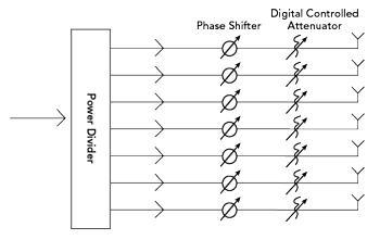
Figure 1 Active beamforming feed network.
An active beamforming network is constructed with power combiners/dividers, digitally-controlled phase shifters and attenuators, as depicted in the block diagram in Figure 1. A key advantage of this type of network lies in the ability to achieve continuous beam sweeping. This capability is facilitated by digitally-controlled phase shifters and attenuators that can provide a broad frequency bandwidth.
These types of devices are currently available in the market. These phase shifters and attenuators typically have a maximum of six bits with the digital control operating discrete phase or attenuation bits that range from the least significant bit value to the combination of all the bit values. The relative bandwidth of phase shifters and attenuators varies across the frequency bands of use, but it is not uncommon to see devices operating in S- and C-Band over a 2.4 to 5.1 GHz frequency range, which equates to a 75 percent bandwidth. Another popular band is the 6 to 18 GHz band, which equates to 100 percent bandwidth. MACOM and Analog Devices reference devices on their websites that operate in Ku-Band, at 24 to 29.5 GHz, equating to 23 percent bandwidth.
However, certain drawbacks come with this technology. The digitally-controlled phase shifters and attenuators necessitate complex control circuitry that includes digital-to-analog converters (DACs) and analog-to-digital converters (ADCs), along with logic control circuits. Additionally, a robust power supply network, effective heat dissipation and temperature-compensation circuits are required to maintain stable circuit performance. In addition to these challenges, information from current publications indicates that the bandwidth is presently limited to a maximum of 100 percent relative bandwidth.

Figure 2 4 × 4 Butler matrix configuration.
Passive Beamforming Networks: The Butler Matrix
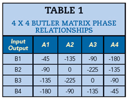
In contrast, a Butler matrix represents a completely passive beamforming feed network for phased array antenna elements. It contains an N x N matrix of hybrid couplers and a fixed number of phase shifters, where N is a power of two. The device features N input ports (beam ports) where power is applied and N output ports (element ports) connected to N antenna elements. It facilitates reciprocal signal transfer between any of the N input ports and any of the N output ports, enabling simultaneous operation as both a transmission and receiving system. The power of two requirement in Butler matrices means that 4 x 4, 8 x 8 and 16 x 16 configurations are typical. Figure 2 shows the 4 x 4 configuration and Table 1 shows the phase relationships among the four output ports.

Figure 3 8 × 8 Butler matrix configuration.
Figure 3 shows the 8 x 8 Butler matrix configuration. This configuration adds another stage of 90-degree hybrids, along with 67.5-degree and 22.5-degree fixed phase shift elements. Table 2 shows the phase relationships among the eight output ports. Note that the phase relationship between output pairs remains the same.


Figure 4 16 × 16 Butler matrix configuration.
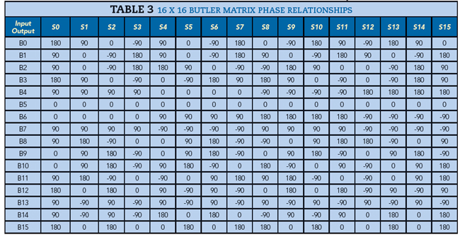
Figure 4 shows a 16 × 16 configuration and there are now four hybrid stages. This configuration is notable because it uses a mixture of 180-degree and 90-degree hybrids and no phase shifters. The phase relationships for this topology are shown in Table 3.
These visual representations offer insights into the matrix’s structure and functionality. Compared to active phased array beamforming networks, the passive Butler matrix boasts a straightforward across-matrix configuration, ensuring accurate and stable performance, higher power handling for each path and cost effectiveness. However, it faces challenges in achieving wide bandwidth with higher phase control accuracy due to limitations in the bandwidth of its components. The factors influencing the bandwidth and performance of the Butler matrix are intricately linked to the design of its passive components, which are based on transmission lines. In the Butler matrix, connections between components are established through transmission lines, where the frequencies of electromagnetic waves have a linear relation with their phase. As shown in the circuit configurations, as the number of input and output ports increases in a Butler matrix, so does the complexity and potential lengths of the interconnections.
To illustrate, an absolute phase accuracy of ±5 degrees over a 0 to 360-degree range implies a maximum relative frequency bandwidth of 2.78 percent for a transmission line. Alternatively, for a 5 percent relative frequency bandwidth, the potential phase accuracy error could be ±9 degrees and for a 10 percent relative frequency bandwidth, the error could be ±18 degrees. In conventional terms, achieving more than 2.78 percent relative frequency bandwidth within 5-degree phase accuracy or obtaining below 18-degree phase accuracy over a 10 percent relative frequency bandwidth is considered challenging, if not impossible.
This underscores a crucial point: to achieve wide bandwidth, every component must support that wide bandwidth with the required phase accuracy and the electrical length error of each path must be meticulously controlled within a very narrow range. Any deviation in these characteristics leads to significant phase changes over a wide frequency range, presenting formidable technical challenges. It is these challenges that have, to date, prevented the emergence in the market of wideband Butler matrices or beamforming networks that also provide high phase accuracy.
MIcable is developing technology to address three areas that are essential for the development of wideband Butler matrices: wideband hybrids, wideband passive phase shifters and accurate phase-matching cable assemblies. Using simulation and optimization tools, coupled with advanced manufacturing processes, MIcable has successfully developed a series of high performance wideband products. Notable in the product portfolio are 0.6 to 18 GHz 90-degree hybrids with a 6-degree maximum phase error and a series of 2.4 to 7.25 GHz passive phase shifters. In addition, MIcable has shipped sets of eight cable assemblies that achieve ±2-degree phase matching among the cables in each group at 28 GHz.
POTENTIAL APPLICATIONS
There is substantial development effort and activity aimed at extending the capabilities of beamforming technology. Innovations in this technology offer advantages to a diverse set of opportunities in 5G, 6G, Wi-Fi, IoT, driverless cars, mobile communication, satellite communication, testing and radar applications. The realization of wideband high-accuracy Butler matrix beamforming networks will enable advances in a variety of applications.
Beamforming Feed Networks for Phased Array Antennas
There is an immediate application for beamforming feed networks in phased array antennas. MIcable Butler matrices can provide stable performance and a straightforward configuration over a frequency bandwidth of 0.6 to 7.25 GHz. Active feed networks struggle to achieve satisfactory performance over a frequency bandwidth this broad. Since the Butler matrix incorporates passive elements, it offers a cost-effective solution with higher than typical power handling capabilities. These devices can handle powers up to 20 W. This set of attributes makes the Butler matrix a compelling choice in these applications.
Channel Simulator in Massive MIMO Systems
Another promising application involves using Butler matrices as channel simulators in massive MIMO systems. They can simulate communication scenarios between IoT nodes, base stations and users. By integrating attenuators on each port, a new type of mesh network emerges with the ability to simulate both the amplitude and phase of signals, surpassing the capabilities of traditional mesh networks.
Object Detection and Allocation
Leveraging the reciprocal signal transfer capability and the ability to feed all input ports simultaneously, Butler matrices can serve as plus and minus networks for signal detection and allocation. This expands the possibilities for detecting and allocating objects in various contexts.
Exploring More Applications
The versatility of wideband high-accuracy Butler matrix beamforming networks implies that more applications await discovery in various industries. As technology evolves, these networks are likely to find novel applications that cater to the specific needs of different sectors.
PRACTICAL EXAMPLES OF BUTLER MATRICES
By developing and integrating wideband hybrids, passive phase shifters and phase-matching cable assemblies, MIcable has produced a portfolio of wideband Butler matrices with high phase accuracy. The specifications of some typical Butler matrix products that have already been shipped are outlined in Table 4. This table shows the broad variety of Butler matrices in MIcable’s portfolio, along with the typical frequency bands and performance that these solutions provide.

ADDITIONAL BUTLER MATRIX CONFIGURATIONS
The table of catalog parts shows a variety of solutions ranging from ultra-high frequencies to Ka-Band frequencies. MIcable has developed a 0.6 to 5 GHz 8×8 Butler matrix. This wideband Butler matrix achieves a phase accuracy of ±11 degrees to ±14 degrees maximum, amplitude unbalance of ±1.0 to ±1.2 dB maximum, insertion loss of 12.3 to 14.5 dB maximum and input/output port VSWR of 1.4:1 to 1.5:1 maximum. This wide frequency coverage addresses the requirements of 5G Frequency Range 1.
MIcable has also developed a 2.4 to 7.25 GHz 8 × 8 Butler matrix. The 8 × 8 Butler matrix exhibits a phase accuracy ranging from ±6 to ±8 degrees maximum, amplitude unbalance of ±0.2 to ±0.4 dB maximum, insertion loss of 9.8 to 10.8 dB maximum and input/output port VSWR of 1.2:1 to 1.4:1 maximum. These results can be achieved across Wi-Fi frequencies of 2.4 to 2.5 GHz, 5.18 to 5.83 GHz and 5.9 to 7.25 GHz. These solutions become more attractive as Wi-Fi 6E/7E applications begin to gain production traction.
The latest addition to the MIcable Butler matrix portfolio is a 0.6 to 7.25 GHz 8 x 8 solution. This device offers ±14 degrees of phase accuracy. MIcable believes that the availability of wideband, high phase accuracy Butler matrices will enable the passive beamforming architecture in more applications.
BUILDING BLOCK PERFORMANCE
As described, there are distinct advantages to using a passive beamforming approach to feeding an antenna array. The Butler matrix provides an excellent solution for these passive beamforming needs, but the viability of this solution depends on the performance of the passive elements. As the desired application bandwidth increases, solving the wideband performance challenge of these passive devices becomes increasingly important.
As an example of the design goals for the building blocks of the wideband Butler matrices, Figure 5a shows the design simulation for the phase accuracy performance of the 2.4 to 7.25 GHz 90-degree hybrid. Figure 5b shows a similar analysis of the phase accuracy performance for the 45-degree phase shifter bit. Similar charts exist for the 22.5-degree and 67.5-degree phase shifter bits, but they are not presented in the interest of brevity.
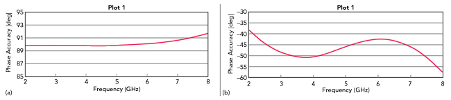
Figure 5 (a) Phase accuracy of 2.4 to 7.25 GHz 90° hybrid. (b) Phase accuracy of 2.4 to 7.25 GHz 45° phase shifter.
As the frequency bandwidth increases, it is not surprising to see the phase accuracy degrade, but the performance is still more than sufficient to meet the needs of the Butler matrix. Figure 6a shows the simulated phase accuracy of the 0.5 to 5 GHz 90-degree hybrid building block. Figure 6b shows the simulated phase accuracy for the 67.5-degree phase shifter bit, the highest required phase shift value.

Figure 6 Phase accuracy of 0.5 to 5 GHz 90° hybrid. (b) Phase accuracy of 0.5 to 5 GHz 67.5° phase shifter.
Measured Results
The simulated results show the performance of the fundamental Butler matrix building blocks, but the better guideline is the actual performance. Figure 7a shows the input port VSWR for the 2.4 to 7.25 GHz 8 x 8 Butler matrix. Figure 7b shows the insertion loss for the same device and Figure 7c shows some representative isolation plots for ports of the 8 x 8 Butler matrix.

Figure 7 (a) Input port VSWR. (b) Insertion loss from input A1. (c) Port isolation.
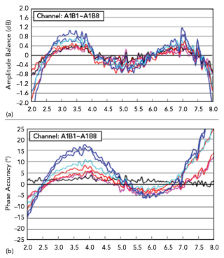
Figure 8 (a) Amplitude balance A1 input to outputs. (b) Phase accuracy A1 input to outputs.
The S-parameter information for the Butler matrix is important, but the function of the device is to route signals to antenna ports that require beamforming and beam steering. As we have described, phase and amplitude imbalance and accuracy become of paramount importance for these applications. Figure 8a shows the amplitude balance for one input of the 2.4 to 7.25 GHz 8 x 8 Butler matrix as compared to all the output ports. Figure 8b shows the phase accuracy for the same input of the Butler matrix to all the output ports.
CONCLUSION
A growing number of applications are relying on phased array antennas to increase capacity, data rates and capabilities. These systems may use active beamforming and beam steering architectures to achieve their performance goals, but these architectures may create issues with cost, power consumption and complexity. Passive beamforming can achieve the same performance objectives and alleviate some of the issues that active beamforming creates. Until recently, the passive building blocks required for a Butler matrix were not capable of the bandwidth and phase accuracy performance necessary to make these solutions attractive to a wide variety of applications. This paper describes the product portfolio, development efforts and results from new products that address the bandwidth and phase accuracy performance that had limited the wider adoption of Butler matrices.