
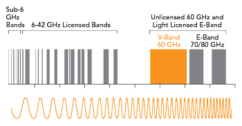
Figure 1 Channel bandwidths for the various communications bands up to 80 GHz. Source: Airvine.
For those seeking the highest bits-per-second transmission rates in the wireless domain, the 60 GHz band has been a gleam in the eye of the wireless community for years. The band has a whopping 14 GHz of spectrum, which is more spectrum than all the sub-6 up to 42 GHz bands combined. There is no doubt that the 60 GHz band offers plenty of bandwidth to achieve multi-gigabit rates. The relative channel bandwidths for these bands are shown in Figure 1.
However, the promise of multi-gigabit systems in this frequency band came with one critical restriction; all operations had to be line-of-sight (LoS), with no obstacles in the transmission path. In addition, any services in this band were and are limited to comparatively shorter-range applications, with link budgets of approximately 1000 m or less. But now, advances in system gain performance and the application of beamforming techniques have solved the LoS problem in interior environments and have resulted in true non-LoS (NLoS) connectivity. The link budget restrictions remain the same, but these restrictions are moot in these environments, as transmission paths rarely exceed 100 m.

Figure 2 Robotic inventory and assembly envisioned in Industry 4.0.
This development opens a whole new market for services in the 60 GHz band, which comes just in time to address applications with burgeoning bandwidth requirements. Industry 4.0 applications aim to address artificial intelligence- and machine learning-based factory operations and backbone or backhaul connectivity for private 5G networks, large data centers and other large interior settings such as conference centers and MDUs are all feeding the need for increased bandwidth and data traffic. This article provides an overview of some of the efforts to develop a market for 60 GHz services. Some Industry 4.0 applications benefiting from high data rate capabilities are shown in Figure 2.
THE BEGINNING
Over the years, there have been several attempts to introduce 60 GHz gear and adopt 60 GHz standards, with mixed results. The WiGig Alliance was founded in 2009 and introduced 60 GHz to the IEEE with the 802.11ad standard in 2012. In 2014, the Wi-Fi Alliance adopted WiGig 802.11ad, as an industry standard certifying WLAN equipment and began a program of interoperability testing.
These efforts failed. The requirement for strict LoS operation in an indoor environment was too restrictive in the home or business environment. Simply walking in between a client and an 802.11ad access point (AP) broke the connection. In addition, APs with built-in WiGig chips were much more expensive than a standard 2.4/5 GHz AP with the cost difference being on the order of hundreds of dollars.
TAKE TWO
The next time 60 GHz appeared on the market was just a few years later with the introduction of IEEE 802.11ay in 2019. The IEEE 802.11ay standard was a significant improvement over 802.11ad in efficiency, range and other characteristics. However, the standard was better suited for short-range applications and the dominant market application that adopted this standard attempted to use it outdoors at ranges of up to 1800 m. The rationale was that if the links had to be LoS, it was easier to do outdoors where devices can be mounted high up on buildings, towers or streetlights. However, this deployment model just served to introduce tension and compromises between the users and the suppliers. Further complicating the situation, this band suffers from oxygen absorption, a phenomenon where O2 molecules in the atmosphere resonate at 60 GHz, absorbing the radio waves, which further attenuates the signals and reduces transmission range. The spectrum is best suited to support applications with links at short distances that meet the LoS requirement. The use case wound up being like trying to fit a square peg into a round hole.
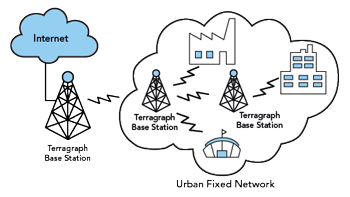
Figure 3 The Terragraph network concept.
The 802.11ay standard served as the foundation for the Terragraph Project, which was launched by Meta, Facebook at the time, to establish a viable ecosystem for outdoor 60 GHz services. This goal was to address residential broadband and particularly, the “digital divide.” As part of this effort, Qualcomm introduced a complete 60 GHz reference design, which included the modem, front-end and antenna. The goal of the project was to reduce total cost and speed time to market for vendors. Figure 3 shows a conceptual block diagram of the Terragraph network.
These systems were point-to-multipoint, meaning the AP or base station had to implement beam steering to overcome the drop in antenna gain caused by 90 sectors in the antenna. This approach served in stark contrast to the very narrow high gain antenna used in point-to-point communications. To improve the business case, broadband wireless access systems relied on increasing the range to cover more clients per base station. This meant pushing these systems to the limits of their capabilities. Since 60 GHz is a short-range frequency with the added obstacle of oxygen absorption, using the band in longer-range deployments was challenging. The Terragraph Project has not achieved the “mass deployment” expectations and Meta stepped away from Terragraph in 2022.
THE SWEET SPOT FOR 60 GHZ
Using 60 GHz indoors matches the inherent short-range performance of these systems to applications that are also short-range. There are no indoor requirements for a one-mile link. It is rare to have a link exceeding 100 m and these links usually range from 25 to 50 m. However, the LoS restriction existed until it became possible to penetrate interior walls and go around corners with beams that can be steered at angles of more than 90 degrees. These new beamforming and system gain capabilities have changed the whole calculus of using 60 GHz and have created a market for indoor cable extension. Using the 14 GHz of available spectrum, it is now possible to realize capacities of 10 to 20 Gbps full duplex.
GETTING BEAMFORMING RIGHT IN THE 60 GHZ BAND
Beamforming involves precise phase shifting the elements of an antenna array to generate a narrow beam focused in a specific direction. The narrow beam increases the gain to the intended receiver, while also reducing interference to other devices nearby. This is useful in sub-6 GHz applications, but the real value comes in the mmWave bands where the additional gain helps overcome high free space path loss and oxygen absorption that occur at 60 GHz.
Beamforming is a foundational enabling technique for all mmWave communications. There are two parts to any radio system: the digital baseband modem and the RF subsystem consisting of the RFIC and the antenna array. Each has a role to play in the beamforming process. The next section presents a high-level overview of the different beamforming techniques currently being used. This will lead to a discussion of MIMO technology, which is a form of spatial multiplexing that leverages beamforming technology.
Analog Beamforming
In systems using analog beamforming, a single data stream is sent from the digital baseband through a radio chain that creates an analog signal in the mmWave band. That signal is then sent through an array of phase shifters to create a narrow beam with high gain. Depending on the design, this antenna gain may be as high as 30 dBi for a large array.
These arrays typically use patch antenna elements that are each about 2 mm2 when operating at 60 GHz. It is possible to have as many as 256 of these elements in an array. By precisely altering the phase and amplitude of each patch antenna element, it is possible to create a narrow beam focused in a specific direction. Since power, as defined by effective isotropic radiated power (EIRP) is limited by regulation, the narrower the beam, the greater the gain as seen by the receiver. As a result, analog beamforming, when used correctly, can create a very high gain antenna.
Digital Beamforming
In this approach, all the phase shifting is done in the digital baseband. This enables precise RF beams and nulls, but this approach does not scale well since a full radio chain is needed for each antenna element. A typical implementation might include 16 data streams flowing through 16 radio chains and then into 16 antenna elements. An attractive feature of digital beamforming is that the technique supports multi-user MIMO (MU-MIMO), which makes it possible to communicate with multiple users over the same RF channel at the same time.
To limit interference, MU-MIMO requires a narrow beam focused on each intended user, with nulls focused on everyone else. Beamforming at mmWave bands is best done with a large number of antenna elements. However, this implementation in the digital domain is cost- and power-prohibitive. A compelling alternative combines the large array capability of analog beamforming with the MU-MIMO capabilities of digital beamforming. This technique is known as hybrid beamforming.
Hybrid Beamforming
This combination of MU-MIMO and analog beamforming is often referred to as massive MIMO. Each beam is structured to deliver maximum energy to the intended user, while also generating nulls aimed at all other users. As users move around in the coverage area, the digital baseband recalculates the necessary changes to phase and amplitude shifts. An advantage of the 60 GHz band is that antenna elements, even for a large array, can easily fit on a PCB of less than 20 cm2. This approach is ideal for access networks that are being deployed in heavily congested areas like stadiums, city centers, convention centers and airports, where it is necessary to connect large numbers of people in a confined area.
Receive Beamforming
Most discussions of beamforming focus on the transmit side of the equation, but the receive side must also be considered. Not only is the RF signal phase shifted across all transmit patch antenna elements, but it must also be phase shifted across the receive side. This allows the receive signals to be properly aligned so that they will add constructively to get a strong signal. This concept is most easily explained by considering a transmitter to the left of the receiver. The receiver antenna elements on the left side of the antenna will see the signal before the elements on the right. These signals must be phased properly to add constructively.
Side Lobes
The creation of RF side lobes is an inevitable part of the beamforming process. There will always be some extraneous RF energy that is not part of the primary beam. These lobes appear as interference to other users in the operating area and they siphon energy from the primary beam that is directed at the intended user. The goal is to minimize this energy to the extent possible. A general objective in any mmWave design is to target side lobe suppression of at least 20 dB. Beamforming is well-suited for mmWave bands. The transceiver and antenna hardware are small and the technique helps counteract the free space path loss challenge while also limiting co-channel interference. The output of a modeled multi-element antenna beam at 60 GHz, with the main lobe and the sidelobes is shown in Figure 4.
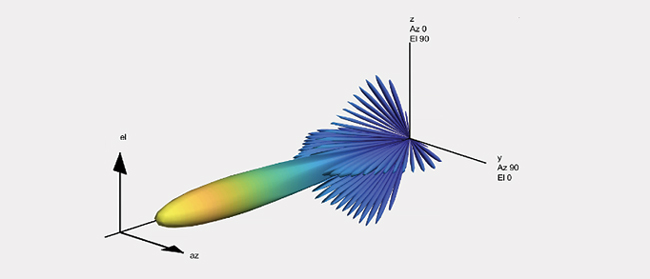
Figure 4 Representative modeled antenna beam pattern.
System Gain Considerations
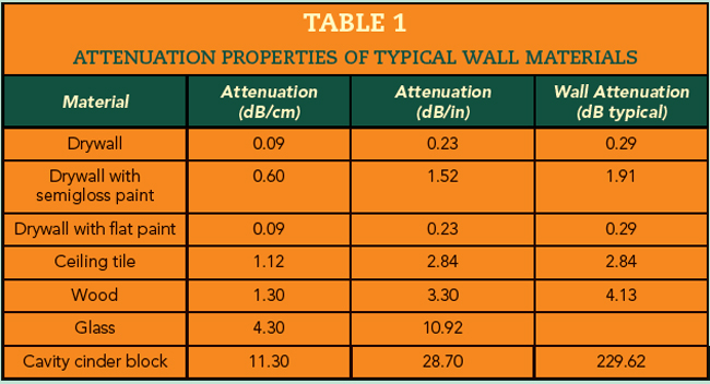
Another big contributor to achieving NLoS connectivity at 60 GHz pertains to improvements in system gain performance. As the operating frequency increases, signal propagation distance decreases. Ultimately, the maximum distance is set when the link performance drops below a specified bit error rate, packet error rate or availability rate. To achieve this NLoS connectivity indoors, penetrating obstacles such as walls is a big challenge, especially since the attenuation of wall materials increases with frequency. For 60 GHz, the attenuation of common indoor walls is well known. Table 1 shows typical attenuation values for various common wall materials and the large variation in loss for these walls is evident.
Range and obstacle penetration performance depends heavily on system gain. This means simultaneously maximizing transmit EIRP (power output plus antenna gain) and receiver sensitivity while getting as much antenna gain as you can fit into a given mechanical limitation. In addition, the FCC and other regulatory agencies have mandated a maximum EIRP of 40 dBm in the indoor 60 GHz application.
The challenge becomes the best way to maximize the allowed system gain plus the receiver gain. Airvine has accomplished this by optimizing the front-end and the antenna to put as much of the EIRP in the antenna. This means narrowing the transmit beam, while at the same time reducing side lobes and other undesired artifacts. The result, in effect, tunes the entire wireless data chain from the modem to the RF transceiver to the antenna, making NLoS connectivity possible in the 60 GHz band. These techniques are the basis for Airvine’s WaveTunnel™ nodes shown in Figure 5. The nodes, coupled with Airvine’s VineSuite control and monitoring software can be configured into a network providing gigabit per second connectivity at 60 GHz in NLoS applications requiring high data rate transmission.
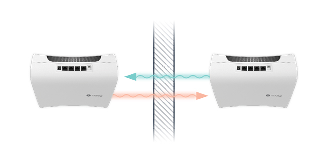
Figure 5 Airvine WaveTunnel node communication through a wall.
CONCLUSION
The future of 60 GHz is not just bright, it is brilliant. Airvine has not violated the laws of physics, particularly the reality that higher frequencies mean shorter ranges. Instead, they have taken a fresh look at the notion that any device operating at a frequency above 6 GHz must be LoS. With careful system-level design, the Airvine WaveTunnel nodes show that NLoS links at 60 GHz are indeed possible. This development is timely as LANs are being pushed to do more and provide a foundation of connectivity for more devices and applications. Most future enterprise and residential applications, along with device use will be indoors, often with a broadband wireless connection. That connection could be Wi-Fi, private 5G or another technology and wireless multi-gigabit backhaul from the AP is now possible.