


Figure 1 Wideband ferrite transformer-based power divider schematic. (T = turns ratio).

Figure 2 Proof of concept.
A wideband very high frequency (VHF) power divider for IoT uses commercially available off-the-shelf ferrite transformers. The measured operating frequency range is from 1 to 400 MHz (a bandwidth of 400:1). Measured insertion loss is less than 0.6 dB and return loss is greater than 18 dB over the entire band. Measured amplitude and phase imbalance are within 0.05 dB and 1.75 degrees, respectively. Isolation is better than 20 dB over the band.
Power dividers are vital components in electronic communication systems and are widely used in high-power solid-state amplifiers, antenna feeder networks, IQ receivers and test and measurement applications. The frequency spectrum allocated for IoT applications has renewed research interest in the VHF Band.1 However, there has been little research in vital components such as power dividers at these frequencies.
A Mini-Circuits application note2 is one of the few references available to designers. However, it uses autotransformers that are not commercially available as off-the-shelf components. In addition, there is no DC isolation between input and output ports in such a circuit. Recently, a magnetic circuit using ferrite transformers has been used to realize a power splitter operating from 200 Hz to 10 KHz (50:1 bandwidth) for power and energy measurements of the smart grid.3 One of its limitations is that it is a custom circuit; it is not possible with this design to employ commercially available off-the-shelf ferrite transformers.
The design described in this article addresses that issue with a wideband power divider using commercially available ferrite transformers (ordinary two-winding ferrite transformers).
POWER DIVIDER CONCEPT
The wideband ferrite transformer-based power divider schematic (see Figure 1) uses only two transformers, one with a turns ratio of 1:1 (i.e. impedance ratio of 1:1) and the other with a turns ratio of 1.414:1 (i.e. impedance ratio of 2:1). Such transformers are available as off-the-shelf components. A lumped resistor with a resistance of 100 Ω between the output ports (Ports 2 and 3) provides the required isolation. Such an ideal network provides perfect impedance matching, power division and isolation; hence, theoretical performance is not plotted.

Figure 3 Simulated |S11|, |S22|, |S33| and |S23|.

Figure 4 Simulated |S21|, |S31| and amplitude imbalance.
PROOF OF CONCEPT
A ferrite transformer-based power divider is designed for operation in the VHF Band with the following specifications: operating frequency range from 1 to 400 MHz, return loss greater than 10 dB, insertion loss less than 1 dB, isolation greater than 20 dB, amplitude imbalance less than 0.2 dB and phase imbalance less than 2 degrees.
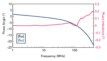
Figure 5 Simulated S21 and S31 phase and phase imbalance.

Figure 6 Prototype VHF power divider.
Design and Simulation
To realize the power divider, two commercially available ferrite transformers from Mini-Circuits: TC2-112G2 (with an impedance ratio of 2:1) and TTC1-33W (with an impedance ratio of 1:1) are employed (see Figure 2).4,5 Measured S-parameters of the transformers are used to obtain the power divider’s simulated response with the Keysight ADS simulator.6 Figure 3 plots the simulated reflection coefficients at the three ports as well as output port coupling. Return loss is greater than 14 dB and isolation is greater than 16 dB over the entire band. Figures 4 and 5 plot the magnitudes and phases of the transmission coefficients respectively, as well as amplitude and phase imbalance. Insertion loss is less than 0.8 dB, amplitude imbalance is better than 0.05 dB and phase imbalance is better than 0.2 degrees over the entire bandwidth. Owing to the symmetry in the simulation environment, both amplitude and phase imbalance are excellent. It is expected that the asymmetry caused by layout in PCB and assembly of components will degrade the amplitude and phase imbalances in the measurement results.

Figure 7 Measured |S11|, |S22|, |S33| and |S23|.

Figure 8 Measured |S21|, |S31| and amplitude imbalance.
Fabrication and Measurement
The power divider is fabricated on a 60 mil 2-layer FR4 PCB (see Figure 6). Figure 7 plots the measured reflection coefficients and output port coupling. Return loss is greater than 11 dB and isolation is greater than 15 dB over the entire band. Figures 8 and 9 plot the magnitudes and phases of the transmission coefficients respectively, as well as amplitude and phase imbalance. Measured insertion loss is less than 1 dB, amplitude imbalance is better than 0.05 dB and phase imbalance is better than 1.5 degrees over the entire band. Note that the power divider demonstrates excellent amplitude and phase imbalance over the entire band even though the layout is not symmetrical. This equates to a power combining the efficiency of better than 99.5 percent, excluding insertion loss.7

Figure 9 Measured S21 and S31 phase and phase imbalance.

Figure 10 VHF power divider with enhanced performance.
PROOF OF CONCEPT – ENHANCED DESIGN
To enhance return loss and isolation performance, a 10 pF capacitor is introduced between the transformers to absorb parasitic inductance (see Figure 10). The prototype power divider is shown in Figure 11. Figure 12 plots the measured reflection coefficients as well as output port coupling. Return loss is greater than 18 dB and isolation is greater than 20 dB over the entire band. Figures 13 and 14 plot the magnitudes and phases of the transmission coefficients respectively, as well as amplitude and phase imbalance. Measured insertion loss is less than 0.6 dB, while amplitude imbalance is better than 0.05 dB and phase imbalance is better than 1.75 degrees over the entire band.

Figure 11 Prototype enhanced-performance VHF power divider.

Figure 12 Measured |S11|, |S22|, |S33| and |S23|.
CONCLUSION
A novel broadband VHF power divider uses commercially available off-the-shelf ferrite transformers. The measured operating frequency range is from 1 to 400 MHz with a bandwidth of 400:1. Measured insertion loss is less than 0.6 dB and return loss is greater than 18 dB over the entire band. Measured amplitude and phase imbalance are within 0.05 dB and 1.75 degrees, respectively, and isolation is better than 20 dB over the band.

Figure 13 Measured |S21|, |S31| and amplitude imbalance.

Figure 14 Measured S21 and S31 phase and phase imbalance.
References
- D. Wright and E. Ball, “IoT Focused VHF and UHF Propagation Study and Comparisons,” IET Microwaves Antennas & Propagation, Vol. 15, No. 8, July 2021, pp. 871–884.
- “AN-10-1006 – Understanding Power Splitters,” Mini-Circuits, Web: www.minicircuits.com/appdoc/AN10-006.html.
- R. Prochazka, J. Hlavacek and K. Draxler, “Magnetic Circuit of a High Voltage Transformer up to 10 KHz,” IEEE Transactions on Magnetics, Vol. 51, No. 1, January 2015, pp. 1–4.
- “TC2-112G2+ Surface Mount RF Transformer Datasheet,” Mini-Circuits. Web: www.minicircuits.com/pdfs/TC2-112G2+.pdf.
- “TTC1-33W-1+, Surface Mount RF Transformer Datasheet,” Mini-Circuits. Web: www.minicircuits.com/pdfs/TTC1-33W-1+.pdf.
- “PathWave Advanced Designer System (ADS),” Keysight, Web: www.keysight.com/us/en/products/software/pathwave-design-software/pathwave-advanced-design-system.html.
- B. Gowrish and R. Kumar, “Analysis of Amplitude and Phase imbalances on Efficiency of Microwave Power Combiner,” IEEE International Conference on Smart Technologies for Smart Nation, August 2017.