
Helical type resonators are widely used for frequencies below 0.5 GHz, mainly for mass and dimensional considerations. Replacing the more traditional TEM combline types or dielectric resonators by helical resonators significantly reduces the size and mass of the filters at the expense of the insertion loss. The rather complicated mechanical structure of the helical resonator sometimes impedes the practical implementation of the cross-couplings necessary for an improved passband response.1 Achieving a reasonably high resonator Q-factor (above 1000) is another design challenge.
A five-element UHF band (370 MHz) bandpass filter using helical type resonators has been developed. A relatively high resonator Q-factor of over 1200 allowed a low insertion loss filter even with a relatively small (for this frequency) size housing. In the process of the filter development several approaches were undertaken in order to improve the skirt selectivity by placing additional transmission zeroes on both sides of the passband. All the approaches were modeled with an Eagleware circuit simulator and experimentally tested. In this article, the circuit models and the theoretical and experimental response characteristics of the filter are presented.

High Q Helical Resonator Experimental Development
The structure of the helical resonator is shown in Figure 1. The terminology and definitions used for the helical resonator are as follows:
-
Resonator diameter, D (center-to-center wire diameter of the loop)
-
Conductor diameter, d0 (diameter of the wire from which the resonator is constructed)
-
Pitch, α (wire center-to-center distance between turns)
-
Number of turns, n
-
Conductor length, L (the overall length of the wire if straightened)
-
Resonator height, H
-
Square cavity width, B
-
Conductor impedance, Z0

The development and investigation of the frequency and Q-factor of a single helical resonator were chosen based on experimental results rather than on well-known formulas.2 A few resonators made of various copper conductor diameters and having D of approximately 0.75" and α of approximately 0.32" were tested inside a rectangular silver-plated test cavity of 1.5" × 1.5" × 1.7", determined by the overall filter size requirement. A (approximately) four-turn helix resonated in the desired frequency range. The unloaded Q-factor, measured with less than –50 dB coupling, demonstrated some improvement with increasing conductor diameter. In particular, resonators with conductor diameter d0 = 0.1", 0.141" and 0.185" gave Qs of 1025, 1121 and 1250, respectively, as shown in Figure 2 for the latter. A tuning screw at the top of the cavity has a significant effect on the resonant frequency, decreasing it (as with the TEM combline resonator), and also degrading the Q-factor. It should be mentioned that firm grounding of the resonator greatly improves the Q-factor.
It was found, that in spite of the fact that a helical resonator is a quarter-wavelength type resonator,2 due to the inter-capacitance between turns, its actual electrical length, determined by the physical length of the conductor, is about 100° to 115°, and depends on the pitch and the diameters D and d0. Further conductor diameter increase was deemed unnecessary because of two factors, the physical difficulty of bending the conductor to the given diameter D and, more importantly, the insignificant Q improvement that could be achieved. Since the conductor diameter determines both the current density and the transmission line impedance Z0 (which is usually greater than 100 Ω2), an increase in d0 will reduce both the current density (losses) over the conductor circumference and Z0. The decrease in Z0 will cause a conductor current increase (as well as losses), so assuming that the Q-factor is mainly determined by losses in the wire, the Q-factor as a function of d0 has a maximum point at a certain conductor diameter for a given cavity size. Based on the experimental results, it is safe to say that a conductor diameter of 0.185" provides a nearly maximum Q-factor for the cavity used.
It is interesting to compare the Q-factor measured experimentally with the empirical relation known in the literature. For the helical resonator dimensional ratios shown, where H = 1.16", and falling within the limits set in Reference 2

The theoretical Q-factor is
![]()
and according to formulas of Reference 3
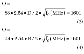
which is higher than the measured value. In any case, it is prudent for engineers to start the development of a helical resonator-based filter with an experimental investigation of a single helical resonator for both Q and frequency consideration.

Circuit Modeling, Prototype Development and Coupling Mechanism
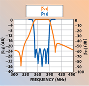
The initial circuit model and response of the five-element helical resonator filter with two triplet cross-couplings are shown in Figure 3 and 4. The initial circuit model was based on the widely accepted representation of a helical resonator filter as a number of capacitively coupled L/C loops.2 At this point, it is assumed that the capacitive coupling results in an asymmetric passband response of the helical resonator filter with a non-abrupt high side skirt. The same type of theoretical response could be obtained with shunt inductances as a coupling means between L/C loops. This model allows the coupling coefficients between resonators as well as external Q-factors of the input/output resonators to be determined. A more detailed assessment of the coupling between helical resonators based on both experimental results and EM simulation will be given below. The inductive elements of each loop shown in the model correspond to an almost quarter-wavelength resonator at the center passband frequency. The capacitive cross-coupling delivering a low side real frequency1 transmission zero (TZ) is modeled as a “real world” lumped capacitive element connected to the first and third filter elements by wires of a certain electrical length (high impedance transmission lines), directly tapped to the resonators, as shown in Figure 5. It seems to be the only way to realize capacitive cross-coupling in the case of the in-line resonator topology (electrically non-adjacent resonators). Due to the fact that each helical resonator has a close to 90° electrical length, its resonant frequency is very sensitive to a small capacitive load change at the top, which makes it impossible to attach the wires at the top of the resonators to be cross-coupled as well as using wires of lower impedance for this purpose. Violation of both requirements results in a severe resonator detuning, which was demonstrated experimentally. It should be noted that a triplet requires rather strong cross-coupling value in order to deliver a transmission zero (TZ) close to the passband.1 Another option for the cross-coupling implementation is a direct opening between the third and fifth resonators configured as a meander. Surprisingly, a full height opening, as shown in Figure 6, resulted in a real frequency TZ on the low side of the passband. Further investigation, based on the HFSS 3D simulation, revealed that capacitive coupling dominates the full height iris opening between two helical resonators. Figure 7 shows a five-element helical resonator filter prototype response with two capacitively cross-coupled triplets, implemented with both a lumped capacitive element between resonators 1 and 3 and through an iris opening (quasi-static electrical field coupling) between resonators 3 and 5. Figure 8 illustrates the electrical field between two resonators, simulated with HFSS. The electrical field is shown to be strong in the space between the resonators, increasing towards the top. It is interesting to mention that the vertical tuning screws shown between helical resonators decrease the electrical coupling as in combline filters.4 Figure 9 shows the HFSS simulated magnetic field between two resonators. The magnetic field lines are mainly concentrated inside the resonators with increased density at the bottom. The outside magnetic field between resonators is weak and provides minimal coupling, which was also proved experimentally. In particular, any attempts to deliver magnetic coupling and, as a result, a right side TZ, via a bottom iris opening2 or via a phase reversing magnetic loop, did not succeed due to the insufficiency of the magnetic field outside the resonator, even at the bottom, and a stronger cross-coupling required for the triplet.1 This observation questions the possibility of the quasi-static magnetic (inductive) coupling between two helical resonators in general. A solution for the inductive cross-coupling as well as proof of the latter statement can be found in Yu and Dokas.5 The eight-element filter described employs a folded structure with two cross-coupling delivering enhanced skirt selectivity (two TZ on each side of the passband) with a flattened group delay response. A direct wire coupling between resonators 2 and 7 delivers the necessary inductive coupling, which produces pairs of real frequency and equalization transmission zeroes, while a slight capacitive coupling between resonators 1 and 8 (iris opening at the top) contributes to the additional real frequency TZ on each side of the passband. The circuit analysis performed for the topology presented in Yu and Dokas5 proved the fact that such a response is possible only with a 270° phase shift (capacitive coupling) between main path resonators.

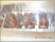
Figure 10 and 11 illustrate the circuit model and theoretical response for the inductive wire coupling approach. Shown in Figure 12 and 13 are a photograph and the response of the prototype unit with the third and fifth resonators inductively coupled by the wire in addition to capacitively coupled resonators 1 and 3. Both TZs on the higher frequency side are contributed by the cross-coupling inductive wire. The first high side TZ is determined by the inductive triplet cross-coupling1 and the second, far out of band TZ seen on both simulated and prototype responses, is caused by the resonance properties of the wire, directly related to the wire length and tap points on the coupled resonators. Obviously, due to the resonant properties of the coupling wire by itself, the phase of the cross-coupled path gains an increased phase slope (dΨ/df), which results in the additional out-of-phase condition met on the skirt.1 It should be mentioned that tuning of a filter with direct wired cross-coupled triplet is rather complex, sometimes resulting in erratic moves of both high side TZs from out-of-band to inside the band frequency region. The physical configuration of helical resonators by itself makes adjustment of the wire physical length and tap point difficult.

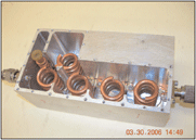
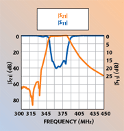
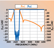
A more successful approach to placing a high side real frequency TZ was based on the addition of a helical trap resonator coupled to the number 5 resonator. Figure 14,15 and 16 show the circuit model, the simulated and prototype responses, respectively. Therefore, in order to deliver a quasi-symmetrical performance with enhanced skirt selectivity on both sides, this approach employs one capacitive through-the-opening triplet cross-coupling (resonators 3 to 5) and a coupled trap resonator. The advantages of such an approach are obvious. First, there is no need for additional parts and soldering joints (lumped capacitance, wires) placed inside the filter cavity, which also may cause parasitic coupling. Second, the tuning is made easier because the location of the high side TZ is determined by the trap resonator frequency only and not by the out-of-phase conditions between two signal paths. Since the Q-factor of the trap resonator is not a critical parameter, its functional dimensions D and d0 can be significantly reduced in order to minimize the effect on the overall filter size.
Cross-coupling Considerations in Helical Resonator Filters and Conclusions
Helical resonator-based filters deliver a high output performance in the UHF frequency band with minimized weight/size of the package, if designed with carefully developed maximized Q-factor resonators. The critical dimensions of the helical resonators should be experimentally verified during the prototype stage in a single cavity of predetermined size. The cross-coupling implementation targeting either skirt selectivity enhancement or group delay flattening (or both) involves a phase computation for signal paths.1,4 Capacitive coupling delivers a 270° phase shift between helical resonators at the center frequency, which makes the implementation aspect of cross-coupling different from the widely used combline and DR-based filters. In particular, in a number of cases, in order to achieve the same cross-coupling effect, for example, for quadruplet (4 to 1) or sextuplet (6 to 1), the coupling between corresponding helical resonators should be inversed (see Table 1) for cross-couplings in a variety of topologies. For the sake of simplicity and best results, the right side skirt selectivity enhancement can be achieved with the addition of a single trap resonator coupled to the input or output element.

References
1. A.D. Lapidus and C. Rossiter, “Cross-coupling in Microwave Bandpass Filters,” Microwave Journal, Vol. 47, No. 11, November 2004, pp. 22–46.
2. A. Zverev, Handbook of Filter Synthesis, John Wiley & Sons Inc., Somerset, NJ, 1967.
3. R. Levy and K.J. Andersen, “An Optimal Low Loss HF Diplexer Using Helical Resonators,” 1992 IEEE MTT International Microwave Symposium Digest, Vol. III, pp. 1187–1190.
4. J.B. Thomas, “Cross-coupling in Coaxial Cavity Filters – A Tutorial Overview,” IEEE Transactions on Microwave Theory and Techniques, Vol. 51, No. 4, April 2003, pp. 1368–1376.
5. M. Yu and V. Dokas, “High Performance Helical Resonator Filters,” 2004 European Microwave Conference Digest, pp. 989–992.

Alex D. Lapidus received his BS and MS degrees in electrical engineering from Polytechnic Institute, Nizhny Novgorod, Russia. In 1991, he moved to the US where he joined the University of California at Los Angeles (UCLA) High Frequency Electronics group and participated in the development of a mm-wave radar and a measuring technique for plasma diagnostic. From 1995 to 2003, he was employed by Microwave Communications Co. International. He is currently involved in the design and development of various filtering systems and passive microwave components with L3 Communications Narda-West, where he holds the position of engineering manager. He has published extensively in the field of microwave/mm-wave components


Alex D. Lapidus
