
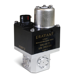
Figure 1 SWJ-08-T1 electromechanical transfer switch.
Electromechanical waveguide switches are widely used in radar, telecommunication and instrumentation systems. With the growth of applications operating above 100 GHz, there is increased demand for electromechanical switches designed for these higher frequencies. To fulfill this need, Eravant has developed full-band WR-08, WR-06 and WR-05 electromechanical transfer switches to cover sub-THz frequencies from 90 to 220 GHz. Typical insertion loss ranges from 1.2 dB for model SWJ-08-T1, which operates from 90 to 140 GHz and is shown in Figure 1 to 2.5 dB for model SWJ-05-T1, which operates from 140 to 220 GHz. Measured insertion loss and isolation results for the WR-05 SWJ-05-T1 switch are shown in Figure 2.
Common to all SWJ models is a compact electromechanical actuator that provides a nominal switching speed of 125 ms. The actuator requires ±28 VDC at 250 mA and a TTL-level control signal to select the switch position. Power and control connections are provided through an MS3112E10-6P connector. Designed for operation from -25°C to +65°C, the switches measure 1.83 × 1.83 × 3.53 in. (46.4 x 46.4 × 89.8 mm) and weigh 7.0 oz. (200 g). They are rated for 100 W of CW signal power. Type UG-387/U-M anti-cocking waveguide flanges are symmetrically positioned 0.675 in. away from the central axis.


Figure 2 Typical insertion loss and isolation for model SWJ-05-T1.

Figure 3 SWJ-XX-T1 switching diagram.
The entire SWJ-XX-T1 series of electromechanical DPDT switches cover full waveguide bands from WR-42 through WR-05 as shown in Table 1. All models use a four-port E-plane waveguide junction as the stator. Using a symmetrical rotor inside the stator, each port is connected to one of its adjacent ports depending on the state of the control signal. Position 1 is selected when a high-level control signal is applied, resulting in a connection between ports 1 and 2 as well as a connection between ports 3 and 4. Position 2 is selected when a low-level control signal is applied, resulting in connections between ports 1 and 4 and between ports 2 and 3. These states are shown in the switching diagram in Figure 3.
Applications for waveguide transfer switches include redundant and reconfigurable transmitters, agile antenna systems and various test and measurement applications. A common application is to optionally select between the orthogonal feeds of a dual-polarized antenna. When used in an antenna test facility, such an arrangement enables the operator to change the polarization of the test signal without disturbing the physical setup. In communication systems with polarization diversity, the polarization of a receiver can be controlled to maintain higher fade margins than would be possible using fixed polarization under variable propagation conditions.
Another common application is in space communication transceivers. Transfer switches on a newly deployed satellite can be used to initially select a higher power amplifier (PA) and a lower gain antenna to establish a communication link with another satellite. After the satellite has established a stable position, a lower PA and a higher gain antenna may be used to conserve power.
Radar and electronic countermeasure systems often require high levels of reliability or periodic self-testing. In these applications, transfer switches can select between redundant components such as PAs or high-sensitivity amplifiers. While one of the redundant components is in service, the other component may be tested or replaced without incurring any loss of service.
In noise calibration systems, waveguide switches are often used to connect a noise power analyzer to either a reference noise source or a tested noise source. By rapidly alternating between two signals, the switch enables accurate comparisons of measured noise levels. This technique will also minimize the effects of temperature drift and other disturbances that could otherwise occur between measurements.
In most switching applications, low return loss, low insertion loss, high isolation and long operating life are desired. The SWJ family provides stable performance over more than 250,000 switching cycles. At frequencies above 100 GHz, innovative designs and advanced levels of mechanical precision are required to achieve these goals. The SWJ series of waveguide switches further demonstrate Eravant’s continued progress into the sub-THz and THz realms with a variety of components used in radar, telecommunication and instrumentation systems.
Eravant, formerly Sage Millimeter Inc.
Torrance, Calif.
www.eravant.com