
The RF industry needs a higher performing filter technology to improve S- and C-Band (i.e., 2 to 8 GHz) tunable filter performance and reduce cost. This article reviews existing filter technologies and describes a new generation of surface-mount, low-power, tunable filters using yttrium iron garnet (YIG) resonators.
The ever-increasing demand for bandwidth is driving the use of higher frequencies, resulting in more spectrum congestion and increasing costs. The wireless spectrum, one of the world’s most valuable natural resources,1 is increasingly crowded.2,3 Demand is outstripping the supply. For example, the Department of Defense reported that unanticipated congestion is requiring increased avoidance planning.4 Putting a value on the resource, in January 2021, the FCC auctioned 280 MHz of spectrum, formerly allocated to satellite users, for 5G cellular and netted $81 billion—over 3x the anticipated amount.5 With global demand for internet data capacity growing at a 50 percent compound annual growth rate over the past three decades, it’s no surprise to see the value of frequency bands skyrocket.6,7
As demand and costs grow, innovative approaches are required for the regulations governing how the spectrum is used, as well as the technologies used in the radios using the spectrum. Using underutilized frequency bands is an important tool to increase spectrum utilization, leading to the adoption of flexible software-defined radio systems and “cognitive radio.” Cognitive radio is a capability for spectrum reuse, where licensed frequency spectrum can be used by non-licensed users on a “first come, first served” basis when it’s not being used by the licensee. When the licensed user requires the frequencies, the “squatter” must immediately switch to other unused frequencies or cease broadcasting until the spectrum becomes available.
RF FILTER TECHNOLOGY
Key to implementing cognitive radio at S- and C-Band is a filter technology that is tunable and, at the same time, provides excellent isolation, low power consumption and small size. Four common technologies are used for RF filters: inductor/capacitor tank circuits, resonant cavities, acoustic (surface acoustic wave and bulk acoustic wave) devices and YIG-tuned filters. Each has strengths and weaknesses when comparing performance, cost, size and power. Since resonant cavity and acoustic filters operate over a fixed band and are not tunable, we only consider varactor (tunable capacitor) and YIG-tuned filters in this article. In some applications, filter banks are used to tune the frequency bands and bandwidth of a radio. However, they are not as flexible as a tunable filter and usually increase board real estate, overall development time and cost.8 Tunable filters provide flexibility for cognitive radio systems and are preferable when they meet system requirements for performance and size.
The performance of a filter is primarily determined by the Q-factor of the resonant circuit, which will set the passband and out-of-band signal rejection. These parameters, in turn, will affect the system noise floor, sensitivity and susceptibility to interference. A higher Q circuit will enable a lower noise floor, yielding greater sensitivity and narrower passband, improving the isolation.
A varactor-tuned filter uses the relationship between the bias on a varactor diode and the diode’s capacitance. Unfortunately, as frequency increases, a varactor’s Q decreases, degrading the filter’s performance. To understand, consider the resonant frequency of an LC circuit:
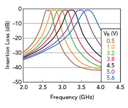
Figure 1 Responses of a tunable filter using a varactor, showing wider passband as the center frequency increases.

Figure 2 Traditional YIG filter configuration, looking down on three YIG resonators configured as a three-pole bandpass filter.

Figure 3 Toroidal electromagnet that surrounds the YIG sphere and generates the DC H-field.

Figure 4 Three YIG resonators housed in a single resonant cavity.
The resonant frequency, fr, is inversely related to the capacitance, C. To achieve a higher resonance, C must decrease. Yet, the Q-factor of the LC circuit is given by9
which shows that as C decreases, Q also decreases. This confirms that as frequency increases, the performance of varactor-tuned filters will necessarily degrade. Varactor-tuned filters generally perform well up to 2 GHz. Above 2 GHz, the bandwidth of the filter increases appreciably with frequency, as shown in Figure 1.
YIG TECHNOLOGY
With varactor-tuned filter performance degrading above 2 GHz, a tunable filter using a new generation of YIG resonators becomes interesting. YIG is a ferrite material that resonates at microwave frequencies when immersed in a magnetic field. Historically, YIG has been used to provide the best performing oscillators and filters, but at a cost. Traditional YIG-tuned oscillators and filters have been large, power hungry and expensive. The theory and construction of YIG-based components is why.
YIG resonators operate when a steady magnetic field, a DC H-field, is applied in one direction, such as the vertical Z direction, and an RF-varying magnetic field is applied from an orthogonal direction, such as X or Y. As with LC tank circuits, a YIG can be used as the resonator in either an oscillator or filter. In a filter, the resonant frequency is the center frequency of the filter, which is set by the strength of the DC H-field.
YIG resonators use polished YIG spheres to take advantage of spherical symmetry, since YIG is sensitive to variations in the magnetic potential across the surface. To minimize the effects of the sensitivity to field variation, each YIG sphere is typically placed in an isolation chamber (see Figure 2). This enables each sphere to be adjusted and tuned without affecting other spheres; however, this isolation complicates the design of the electromagnet creating the H-field.
Magnetic power is coupled through magnetic media, i.e., a ferrite material. Conceptually, this is like power conducted via wires through electrical media. Extending the analogy, magnetic power is dissipated when the magnetic field encounters “reluctance” in the same way electric power dissipates when current encounters resistance. The geometrical design of the YIG filter requires a YIG sphere to be inserted in the gap of a toroidal electromagnet (see Figure 3). The width of the air gap in the toroidal electromagnet is directly related to the reluctance of the electromagnetic circuit. The wider the air gap, the greater the reluctance, the greater the magnetic loss in the circuit and the larger the supply required to generate the H-field.
As noted, traditional YIG components are large and consume a lot of power, a result of the geometry of the design. The frequency of operation, the number of YIG spheres with each sphere occupying its own chamber, the size of the air gap and the size of the electromagnet needed to tune the YIG to the desired frequency result in the large size and power consumption of traditional YIG designs. For frequencies in the 1 GHz range, the electromagnet can be relatively small. Tuning the YIG to 2 GHz requires twice the magnetic field strength and twice the number of turns in the electromagnet, the magnetic field strength and attendant size of the electromagnet increases with the operating frequency. Also, the complex assembly of the component, not amenable to mass production, increases the cost.
ADDRESSING THE SHORTFALLS
To address the downsides of traditional YIG components, VIDA Products has developed a new generation of YIG-tuned filters. The goals are maintaining YIG’s high Q performance while decreasing the size and power consumption by up to 10x and significantly lowering the manufacturing cost. Lowering the power consumption would make YIG technology an option with battery-powered systems.
Reducing and eventually eliminating the air gap is the key to decreasing the size and power requirements of the YIG resonator. The approach involves the sphere-to-sphere coupling technique and adopting a single resonant cavity. The proprietary techniques for accomplishing both led VIDA Products to develop its “Next Generation” YIG filters. The design houses three YIG resonators in a single resonant cavity (see Figure 4). The RF input and outputs are microwire loop-coupled, and the internal coupling is sphere-to-sphere.
Comparing the filter performance of this new YIG technology with varactors, varactor-tuned filters provide from 15 to 40 dB isolation at S- and C-Band, while YIG-tuned filters achieve more than 70 dB.10 For a tuned center frequency of 4 GHz, the bandwidth of a varactor-tuned filter is between 120 and 400 MHz, from 3 to 10 percent, which increases with frequency (see Figure 1). Since the bandwidth does not remain constant with frequency, the system is more susceptible to noise and interference at higher frequencies.11

Figure 5 Tunable YIG filter responses at 2.2 (a), 3.3 (b) and 4.4 (c) GHz, keeping the passband at approximately 40 MHz.