Models make or break the accuracy of a simulator. Although modern simulators have a wide range of models, device technology continually evolves, requiring new ones. Creating linear models is easy and straightforward. Nonlinear models, however, have been so difficult to create that engineers are often forced to live with existing models rather than create custom compiled models.
To make creating nonlinear models much easier, Eagleware Corp. has introduced GENESYS 2003.10, which includes a powerful Verilog-A compiler as part of an extensive Advanced Modeling Kit. The unique advantage of the Verilog-A compiler is that it combines the power of a standards-based model with execution speed previously available only in native C models. Using technology provided by Tiburon Design Automation (Santa Rosa, CA), this release is believed to be the first commercial shipment of a Verilog-A compiler. In addition to the compiler, the GENESYS Advanced Modeling Kit contains a set of 12 advanced nonlinear models such as the HiSIM MOSFET model.1
Verilog-A
Verilog-A is an extension of base Verilog defined by IEEE 1364 and has been proven to be a suitable language to describe analog models.2 Verilog-A interpreters are available from several analog simulators such as Spectre from Cadence. However, these interpreters execute too slowly for use with large simulations. The new Verilog-A compiler included with the Advanced Modeling Kit overcomes this speed limitation by converting Verilog-A into true C-coded models automatically and transparently to the user.

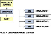
Figure 1 shows how a single source code file can be used with any simulator that supports the Verilog-A Run Time Environment (RTE). Today, that simulator could be any of the GENESYS circuit simulators; in the future, the same compiled program could be used with any simulator that supports compiled Verilog-A, such as Agilent's ADS (in July 2003, Agilent announced plans to provide Verilog-A support in a future release3).
Two clear benefits of compiled Verilog-A are faster, easier implementation of nonlinear models and improved model-sharing, which comes with a standards-based model.
Fast and Easy Modeling
Implementing a native nonlinear model in SPICE or most other simulators requires about 10,000 lines of code written in more than 40 different routines. A separate set of routines must be completed for each simulation type (DC, AC, harmonic balance, etc.). As the program must be written in a general programming language such as C or C++, the models are built from the ground up.
In contrast, implementing a model using Verilog-A typically takes one-tenth the number of lines of code, speeding development and reducing errors. For example, one of the most tedious and error-prone portions of modeling is calculating function integrals and derivatives. Using Verilog-A, the charge function is defined and the complier symbolically calculates all required derivatives and integrals. In addition, current and noise contributions are easily defined using built-in functions.
A simple example of how modeling is made easier is shown in parameter definition and range checking. Typically, model parameters have default values and limited valid ranges. For example, in a pn diode model, the zero-bias junction capacitance has a default value of 0 and can be any positive number. The Verilog-A statement that describes this is simply
parameter real cjo=0 from [0:inf];
In the case of the junction potential, Vj, the default value is 1 and can accept any value except 0. The Verilog-A that describes this is
parameter real vj=1.0 exclude 0;
After simply defining the parameters, the Verilog-A compiler takes care of the actual parameter checking and error message generation. The complete implementation of the diode model can be found on the Eagleware Web site at http://www.eagleware.com.

|
Table 1 | |||
|
MOSFET |
MESFET |
BJT |
Other |
|
BSIM4 |
Parker-Skellern |
MEXTRAM |
Philips JUNCAP |
|
HiSIM |
Angelov (Chalmers) |
UCSD HBT |
Thin film transistor |
|
MOS EKV |
|
Thermal BJTT |
Varistor |
|
MOS-9 |
|
|
|
|
MOS-11 |
|
|
|

Standards-based Modeling
Many benefits are derived from implementing models using a standards-based language. First, models can often be implemented using public-domain code. For example, Verilog-A for the VBIC model is available on the VBIC home page.4 Secondly, and more importantly, once a model has been developed in Verilog-A, it can then be used in any simulator that supports the language. Many companies and foundries have custom models that must be implemented into multiple simulators. In the past, this has meant multiple engineering-weeks of work per simulator. The work was so great that the models were not implemented in all simulators, limiting access to simulation technologies that were of value to engineers. By using a standards-based model, supporting multiple simulators becomes much easier and straightforward.
Verilog-A Architecture
The key components of the architecture are a stand-alone compiler that generates a dynamically linkable library and a run-time environment that is customized to particular simulators. The advantages of this architecture include an efficient distribution process, extendable support for existing and new analysis types, and fast execution.
Advanced Device Models
The GENESYS Advanced Modeling Kit includes device models for a range of new MOSFET, MESFET, BJT and other device models (see Table 1 ).

Other GENESYS 2003.10 New Features
In addition to the Advanced Modeling Kit, GENESYS 2003.10 has a rich set of new capabilities and products for RF and microwave engineers, including:
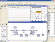
- SIGNAL CONTROL Synthesis: over 30 topologies of splitters and couplers can be synthesized based on input parameters, such as coupling factor and bandwidth (see Figure 2 ).
- Enterprise Capabilities: to meet the needs of groups of engineers and complete company needs, GENESYS includes features such as a part library manager, XML input and output, connections to corporate databases, Visual BASIC scripting and Agilent ADS file export (see Figure 3).
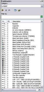
- Substrate Dependent Libraries: eight new device libraries (four capacitor and four inductor families) extend the coverage of surface-mount part libraries with unparalleled accuracy that accounts for substrate dielectric constant and thickness variation.
- General User Interface Improvements: revamped data graphing, design file management and extended units support.
- Improved System Simulation: new hybrid amplifier model and support of up to the 20th order intermodulation products (see Figure 4 ).
Conclusion
The latest release of GENESYS adds new power that helps both individual engineers and companies. The Verilog-A compiler technology will help the entire RF simulation industry adopt and propagate new advanced nonlinear models that enhance the accuracy of simulation.
References
1. http://www.cr.org/publications/MSM2002/pdf/361.pdf.
2. L. Lemaitre, C. McAndres and S. Hamm, "ADMS - Automatic Device Model Synthesizer," CICC 2002.
3. http://www.agilent.com/about/newsroom/presrel/2003/22jul2003a.html.
4. http://www2.fht-esslingen.de/institute/iafgp/neu/VBIC/index.html.
Eagleware Corp., Norcross, GA (678) 291-0995, www.eagleware.com. Circle No. 306
