
DESIGN AND FABRICATION
Depending on the application and the required direction of the radiation, either TE or TM modes may be desired. In addition, in many applications, a wide radiating bandwidth formed by the same type of radiating modes is desirable. The DRA design presented herein has an air center (see Figure 8) to provide a wide radiating bandwidth formed by multiple TE modes. It accomplishes this by suppressing side-radiating TM modes within the radiating frequency band and shifting the spectral location of the TM modes to higher frequencies. Figure 9 shows a representative gain and |S11| of the DRA and depicts a wide radiating bandwidth of TE modes. Such DRAs can achieve TE mode radiating bandwidths of over 40 percent.

Figure 9 Representative DRA gain and |S11| showing the wide radiating bandwidth of TE modes.
Wideband DRAs described in this work are multi-layer with an air center and a dielectric portion containing an inner layer having a dielectric constant of 10.5 and an outer layer having a dielectric constant of 2.1. The inner layer is a thermoplastic filled with filler particles, and the outer layer is unfilled PTFE. All dielectric portions are CNC machined and the inner layer is pressure fit to the outer layer. The DRA includes a coaxial feed and an aluminum reflector cavity to provide isolation between adjacent DRAs in an array. Figure 10 shows the fabricated components and the assembled DRA. Two types of DRAs are fabricated, one with a metal reflector base size of 20 × 20 mm (referred to as unit 1), and the other unit with a metal reflector base size of 22 × 22 mm (referred to as unit 2).
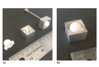
Figure 10 DRA fabricated components (a) and assembled (b).

Figure 11 Simulated vs. measured |S11| of the two DRA units over frequency.
RESULTS AND DISCUSSION
Individual Antenna Elements
The DRA units are each measured with a vector network analyzer (VNA); |S11| versus frequency shows good agreement with simulation (see Figure 11). |S11| is less than -10 dB from slightly under 8 to slightly over 12 GHz, providing a measured impedance bandwidth of 43 percent. Furthermore, |S11| is insensitive to the size of the metal reflector, which is indicative of high mode confinement to the dielectric structure and the cavity. Also, |S11| of the measured units exhibits distinct minima in the matched band from 8 to 12 GHz, which is attributed to the various TE modes supported by the DRA.
Figure 12 shows the measured gain on boresight of the DRA units, which corresponds closely with the simulation and is consistently high from about 8.75 to 12 GHz due to the presence of adjacent TE modes in the frequency spectrum. A single DRA unit is simulated and measured boresight gain is about 8.2 dB at 10 GHz. Furthermore, RF simulations show that the DRAs have radiation efficiencies greater than 95 percent over the entire 8 to 12 GHz band.
To understand the benefits of the 3D nature of the DRA design, the aperture efficiency of a 20 × 20 mm aperture, with no additional ground, is calculated using the well-known formula:
![]()
where G is the gain of the antenna, A is the base area of the antenna aperture and λ is the wavelength.
At 10 GHz, the measured gain is 8.2 dB for the 20 × 20 mm DRA, and hence the aperture efficiency based on the equation is calculated to be 118 percent. It is greater than 100 percent because the formula provides the aperture efficiency for a 2D aperture, where the true aperture for a DRA is the entire curved radiating surface encompassing the DRA element.
Figure 13 shows E-plane and H-plane radiation pattern measurements at 10 GHz for both DRA units. The measurements demonstrate that the reflector size beyond 20 × 20 mm has little influence on boresight gain, indicative of the radiation mode source being dominantly controlled by the EM mode in the dielectric portion of the DRA.
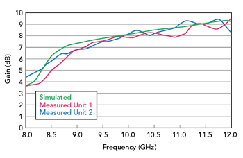
Figure 12 Simulated vs. measured boresight gain of the two DRA units over frequency.
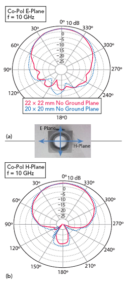
Figure 13 Measured E- (a) and H-plane (b) antenna patterns of the two DRA units.
Array Antenna
To demonstrate the array performance of multiple DRAs in a typical steerable configuration used for various applications, a 5 × 5 DRA array is created. Figure 14a is a photograph of the 5 × 5 array of DRAs, where each DRA is fed with separate coaxial feeds. The assembly is contained within a frame that holds all the DRAs. Figure 14b shows the 5 × 5 DRA array fed with a Rotman-Turner lens for steering the resultant radiated beam up to angles of 30 degrees.
Figure 15 shows simulated and measured radiation patterns of the 5 × 5 DRA array at 10 GHz along the steering direction plane for the Rotman-Turner lens beam ports associated with 0-, 10-, 20- and 30-degree steering angles. The results show good agreement between measured and simulated radiation patterns.

Figure 14 DRA array (a) and array assembly with a Rotman-Turner lens feed (b).

Figure 15 Simulated vs. measured radiation patterns of the 5 x 5 DRA array at 10 GHz.
CONCLUSION
A very efficient, wideband and steerable DRA at 10 GHz is based on the radiation properties of a multi-layer dielectric resonator. The radiating bandwidth is maximized via an interplay between TE and TM radiating modes. The resonator shape, multi-layer structure and unit cell architecture favor multiple TE radiating modes in spectral proximity. Furthermore, radiating TM modes are suppressed and shifted to higher frequencies utilizing an air center. The technique provides a flat and high boresight gain over a wide frequency band. DRA designs are scalable over a broad frequency range from C-Band to automotive radar frequencies and beyond. We strongly believe that the technology provides valuable tradeoffs that cannot be readily achieved with conventional antenna technologies.
ACKNOWLEDGMENTS
We thank Stephen O’Connor at Rogers Corporation for material formulation. We also thank Shawn Williams, Karl Sprentall and Bob Daigle at Rogers Corporation for valuable discussions and feedback.
References
- Y. Kobayashi and T. Senju, “Resonant Modes in Shielded Uniaxial-Anisotropic Dielectric Rod Resonators,” IEEE Transactions on Microwave Theory and Techniques, Vol. 41, No. 12, December 1993, pp. 2198–2205.
- K. A. Zaki and A. E. Atia, “Modes in Dielectric-Loaded Waveguides and Resonators,” IEEE Transactions on Microwave Theory and Techniques, Vol. 31, No. 12, December 1983, pp. 1039–1045.
- E. Snitzer, “Cylindrical Dielectric Waveguide Modes,” Journal of the Optical Society of America, Vol. 51, No. 5, May 1961, pp. 491–498.