A new product line of ultra linear bandpass filters has been introduced that utilize patent pending cross coupling to reduce time delay and phase distortion up to 90 percent. The filters typically utilize a 12-section filter with two inductive and two capacitive non-adjacent couplings to equalize and flatten the time delay response and increase the close-in rejection. The number of sections and non-adjacent couplings, along with the coupling values, will vary depending on user's requirements and passband frequency.

The key benefit of the patent pending cross coupling technique used with the new filter line is the ability of the technician to change the value of the cross coupling without opening the filter. Conventional capacitive cross coupling utilizes a transmission line that couples two non-adjacent cavities together. The value of this coupling is typically changed by opening the unit and making small adjustments to the coupled ends of the transmission line. This operation is time consuming and degrades the reliability of the filter, as it increases the chance for debris to enter the cavity. Also, the threaded holes that fasten the cover can become worn, degrading the reliability. Other reliability concerns with conventional cross coupling are the coupled ends of the transmission line that are typically difficult to secure well enough to ensure they will not continue to move, especially in a high vibration or shock environment.

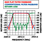
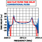
This new design is much more reliable than conventional capacitive coupling structures, and has been qualified on several spacecraft requirements. In-house qualification testing with this design subjected the component to a three-axis 250 G shock, and 100 cycles of +85° and -50°C temperature without failure. The design has also passed HALT/HASS testing that simulates years of service. A major wireless OEM subjected 12 units to HALT/HASS testing, without a single failure. Multiple inductive cross coupling allows the filters to be specified with less than 2 ns of delay variation across the matched bandwidth. Phase performance is also optimized with a typical distortion of less than 10° over the matched bandwidth. Multiple capacitive cross couplings also offer superior rejection with the 60 dB bandwidth at a ratio of less than 1.3 of the passband. These performance numbers are based on a 12-section elliptic filter with two inductive and two capacitive non-adjacent couplings. A comparison of the passband response of this design vs. a conventional filter construction is displayed in Figure 1 . Figure 2 shows a similar time delay comparison.
Delta Microwave,
Oxnard, CA (805) 240-1044,
www.deltamicrowave.com. Circle No. 304
Linear Phase and Group Delay Effects
In the relationship between phase and group delay, group delay is the derivative of the phase. Typically, the phase has a cubic shape so the group delay will have a parabolic shape with the familiar rabbit ears. Ideally, it is desired to have a linear phase, which in effect would create a constant delay over the operational frequency.
For an example, take an EM signal traveling through space. If the group delay is not flat over frequency then the different wavelengths in a signal would arrive at different times. The greater the time delay across the operating bandwidth, the greater the difference in arrival time at the receiver. This is known as "dispersion" because if the signal, for instance, is a pulse, the pulse shape would start to disperse and become wider as the delay variation across the pulse's spectrum increases. An example of a three-dimensional dispersion effect is seen with white light shining through a prism. The different colors have different delays so the shape of the prism causes the wavelengths to separate and disperse.
In a communications channel, sending a BPSK signal, for instance, the pulse shapes will distort and interfere with each other causing intersymbol interference. A pattern known as an "eye pattern" can be generated when the bit patterns overlap each other. As the distortion increases the zero crossing for the bits will move around depending on how many consecutive 1s and 0s exist, causing the eye to become more closed in the center. The eye pattern gives an idea of what the bit error rate (BER) of the system will be. As the eye closes, it gets harder to detect whether a 1 or 0 was sent. The bottom line is group delay variations across the band will distort the signal and make the BER worse.
