In today's competitive marketplace the characterization of RF semiconductor devices for modeling, design, applications and process improvement must be faster, more efficient, and more repeatable and accurate as companies strive to improve their product performance, design productivity and time to market. However, help is on hand with the Wavevue Measurement Studio™. This software is designed to meet the demanding requirements of RF device characterization by integrating all of the tasks of calibration and measurement, data collection, data archiving and analysis, and comprehensive reporting and export of data into a single, easy-to-use package. It is designed for on-wafer, fixtured and module applications so the same software can be used as products flow vertically throughout an organization.
It has a modular architecture allowing users to add measurement functionality as they need and enables future expansion. Currently, DC curves and DC biasing, S-parameter characterization, and wafer and temperature control are supported.

A Total Package
Wavevue is a total solution serving the needs of all members of the characterization and design teams both in the lab and in their offices. A typical workflow is shown in Figure 1 , where a test engineer running the Office Edition sets up a project that defines all the measurements and reports. The project is then stored on the server and retrieved in the lab by the operator, who, using the Instrument Edition, runs the measurement script.
Data is stored back on the server and is then available to the design, modeling and process engineers using the Office Edition. They can then export to CAD applications, generate user-defined reports, compare new data with previously measured data, etc. This process ensures tests on a particular device are performed repeatably regardless of the operator.
Architecture
A common software shell enables all the current and future measurement modules to share file and data object management, report creation, scripting, instrument set-up, project management and data analysis functions. Users log in and the software remembers their specific preferences, recent projects and corporate access level. The user preference file follows users around the network so that no matter where they log in, they are always in touch with their projects and data.
Furthermore, a 'project' model organizes the various file components of a test definition. Instrument and measurement set-ups are separate such that equipment can be changed without affecting the parameters of the basic measurement set-up. A simulation mode allows new users to build projects and test them in their office prior to entering the lab. New users can take advantage of pre-built standard projects for passive devices, FETs and bipolars, while more experienced users can select a 'New' or 'Existing' project to develop their test plan.

Reports and Data
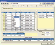
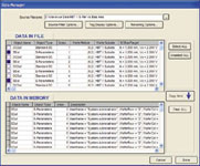
A powerful feature is the extensive report generation capability. The Report Manager (see Figure 2 ) helps users create reports that can then be combined into custom layouts (pages). All the most common types of reports (X-Y, Smith, polar, wafer maps, tabular) can be provided but Wavevue's power lies in its ability to arbitrarily slice across multi-dimensional data and combine data from different measurement objects in a single plot. An extensive data fitting capability enhances the ability to present meaningful data. Parametric sweep plots (S11 versus frequency swept versus wafer reticle, for example) can identify trends that are not commonly seen. The Data Manager (as shown in Figure 3 ) enables users to selectively retrieve data from many previous measurement sessions (files) and combine it with measurements in memory for comparison in reports.

CAD Links and Exports
The software exports S-parameter data in Touchstone format (S2P), ICCAP compatible format (MDM) and MDIF (S2D, generalized) format. Tabular reports can be exported as ASCII text and all graphical reports as Windows Metafiles. Direct export of reports and layouts to Microsoft Word is also supported. S-parameter data can also be imported in S2P format and displayed in reports with other measured data.
Scripting
All measurements are ultimately defined and executed using scripts. Basic scripts are generated automatically when a user creates a measurement set-up, which can be added to using a graphical interface. This is an important feature since users are not required to learn the syntax of the script language.
Script capabilities include file I/O, measurement and calibration execution, user prompts, report display, automated data export and programming loops for bias, temperature and reticle. Generic control of user defined instruments and real-time data streaming during measurement are also supported.
S-parameters and DC Applications
The S-parameter module supports extensive control of both calibration and measurement set-ups for one- and two-port measurements. Users have control over sweep types, averaging, power levels and numerous other functions. A power compression check allows users to determine if the power level selected is appropriate for their device. All the equipment for the measurement is set up automatically or alternatively, and users can set up the network analyzer manually and upload all settings for storage in the project.
Since many devices require additional de-embedding of parasitic elements, two methods are provided: standard input/output network de-embedding, and probe pad parasitic removal. The latter technique supports measurement of the standards in situ, and embedding of networks is also supported.
The software provides the tools to bias the device under test automatically in order to perform S-parameter versus bias studies, potentially across a wafer and versus temperature. Up to four channels of bias are supported and each channel can be provided by a distinct power supply.
A device set-up wizard assists with the details of setting up each channel of bias including source mode, monitor channels, sequencing and timing. Users can also manually set current and voltage alarms/limits, and start and end point criteria for bias searches (Vd Id on a FET, for example). DC targets can be ranges, individual bias points or combinations of both.

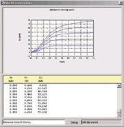
Also, the DC Curves feature means that the desired operating point of a device can be achieved. Figure 4 shows the common emitter curves for a bipolar device. The range of Vc and Ib were specified and the software measured the corresponding Vb and Ic.
Wafer Probers and Instrument Control
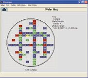
Wavevue is fully integrated with Nucleus™, the control software for Cascade Microtech automated wafer probers. Users can set up wafer and subsite maps and transfer them directly to Nucleus. Existing wafer maps in Nucleus can also be uploaded to Wavevue. Complete script control for the prober movement and chuck temperature is provided in order to facilitate the generation of wafer maps, as shown in Figure 5 .
Another feature is that measurement modules selectively enable drivers for instrumentation related to that specific module. Users simply add the desired instrumentation to the instrument workbench. The S-parameter module supports most network analyzers from the major manufacturers, including new millimeter-wave systems.

Conclusion
A software solution has been presented that provides an alternative to in-house software development for device characterization and data presentation and analysis. A key advantage is that it enables users to achieve greater productivity during the modeling and design cycle. Furthermore, it is fully integrated with wafer probing and calibration solutions, and is expandable to meet future needs. Finally, near-term plans include the introduction of modules for capacitance (CV) and parametric (IV) measurements.
Wavevue Measurement Studio™ and Wavevue™ are trademarks of Microvue Inc. Nucleus™ and WinCal™ are trademarks of Cascade Microtech Inc.
Cascade Microtech Inc.,
Beaverton, OR (800) 550-3279,
www.cascademicrotech.com.
In Europe, Tel: +44 1295 812828, e-mail: cmesales@cmicro.com
or
in Japan, Tel: +81 03 5478 6100, e-mail: sales@cmj.co.jp. Circle No. 301
