
5G New Radio (NR) is the first standard to use the mmWave frequency region for highest data transfer rates. The highly integrated front-ends and array antennas necessitate advanced over-the-air (OTA) testing methods and new RF test metrics for assessing current and future mobile communication. Such test metrics include virtual cable calibration (VCC), which is mandatory for reproducible and reliable OTA throughput testing. For performance tests where fading is emulated - such as radio resource management (RRM) conformance and demodulation testing - the VCC method is crucial to assess defined antenna correlations with minimal crosstalk from the OTA link. The measurement results presented in this article demonstrate the proposed concepts for VCC can be applied to ensure device compliance to the 3GPP standard.
5G has pioneered the use of mmWave frequencies with large bandwidths to enable the reliable, high data transmission rates necessary for demanding real-time applications with low latencies. To increase the system capacity, as well as data rate, and to handle diverse services, 5G NR deploys at much higher frequencies and bandwidths compared to LTE, as well as very high configuration flexibility. A signal bandwidth of up to 400 MHz can be used in 5G NR, compared to 20 MHz in LTE. Since the spectrum below 6 GHz is already used extensively, high bandwidths are only available at higher frequencies, with two mmWave frequency ranges identified (see Figure 1). The overall bands used for 5G NR are:
- Frequency range 1 (FR1) spans frequencies from 410 MHz to 7.125 GHz.
- Frequency range 2 (FR2) is the spectrum from 24.25 to 52.6 GHz.
- For future extension, the frequency range designated FR2+ covers 52.6 to 71 GHz.
5G technologies such as massive MIMO and beamforming further increase the complexity of testing user equipment (UE), as defined in 3GPP TS 38.521-4,1 where highly integrated antennas require radiated test methods.
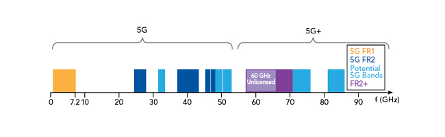
Figure 1 Designated 5G NR frequency bands (FR1, FR2 and FR2+) and possible future bands.
VCC FOR 5G MIMO
One of the biggest challenges for test and measurement manufacturers is implementing standardized evaluation and verification methods for UE under repeatable and realistic conditions, which are also reliable with mass production processes. For LTE and 5G NR FR1 tests, conductive testing methods are the norm for MIMO devices. During testing, the antennas of the device under test (DUT) are disconnected from the antenna ports, and the DUT is directly connected to the test system using a coaxial cable (see Figure 2). However, for testing UEs in the FR2 bands, this approach is not practical: the large number of integrated antennas on the UE for spatial multiplexing and beamforming requires testing OTA, without cable connections.

Figure 2 UE testing for 2 x 2 MIMO with channel fading, showing connected (FR1) and OTA (FR2) approaches. OTA testing introduces unwanted crosstalk.
OTA testing introduces challenges. The transmitted signal propagating in the air channel, represented by OTA Channel A in Figure 2, is affected by other signals and noise, becoming distorted. To have defined and reproducible conditions similar to conductive testing, the effects of the OTA channel must be eliminated. One approach to solve this issue is to calculate the unknown transfer matrix A by accounting for the complete OTA environment, including the transmitter and receiver antenna characteristics. This approach is complex and, in most cases, not possible: UE manufacturers are not required to give detailed information about their antenna characteristics, including the phase information required to apply this method.
An alternative approach, described here, equalizes the channel matrix using only the Reference Signal Received Power per Branch (RSRP-B) feedback parameters, which can be retrieved from an FR2 UE per the 3GPP standards. This enables having a quasi-conducted or “virtual cable” connection or “virtual cabling” in an FR2 radiated test environment.2 The approach lays the foundation for practical 5G UE performance testing for maximum throughput, as well as testing under various channel conditions, such as fading. An equalized channel is also mandatory for conformance tests with fading, which are needed for RRM tests.
SIGNAL QUALITY USING RSRP-B FEEDBACK
The secondary synchronization RSRP-B (SS-RSRP-B) is defined as the linear average power per branch, in watts, of the resource elements that carry secondary synchronization signals. For FR2, the SS-RSRP-B is measured for each receiver branch based on the combined signal from the antenna elements corresponding to the receiver branch. The RSRP-B is an important parameter to assess signal quality, and it is the UE’s task to calculate the SS-RSRP-B and fulfill the accuracy requirements. The power per resource element is determined from the energy received during the useful part of the symbol, i.e., excluding the cyclic prefix. In 5G NR, RSRP measurement is performed and reported at layer 1, the physical layer, and layer 3, the radio resource control (RRC) layer. For example, a 5G capable device can provide SS-RSRP measurements at layer 1 when sending channel state information and at layer 3 when sending an RRC protocol measurement report to the next-generation node B (gNB).
The level 1 measurements are relevant for the following implementation, and the SS-RSRP-B reporting range is defined from -140 to -40 dBm with 1 dB resolution. The RSRP-B is the linear average power measured at each receiver branch of the DUT. 3GPP requires the 5G NR FR2 device to support RSRP-B, which enables the determination of a calibration matrix which can equalize the channel.
CALIBRATION METHOD
As propagation conditions and antenna characteristics are the most important factors for field performance of MIMO devices, mobile receiver performance tests must include these parameters. These conditions are generally simulated through a fading simulator or channel emulator. The channel emulator is a measuring instrument for reproducing the actual radio wave propagation environment described by the matrix F(f,t), which can include dynamic scenarios in moving environments. It reproduces the fading environment defined by 3GPP and the virtual environment of multiple MIMO channels.
As shown in Figure 3, the UE is placed in a controlled wireless environment, such as an anechoic chamber, to minimize the distortions caused by multipath propagation and reflection. The setup in the figure shows the case of 2 × 2 MIMO; however, the concept can be extended to N × N, where N > 2.
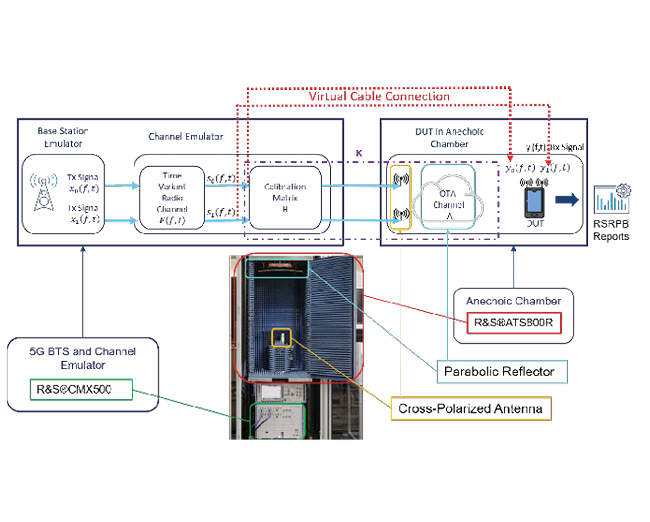
Figure 3 Setup for calibrating 2 x 2 MIMO OTA measurements.
For development and conformance tests, the base station emulator simulates a mobile 5G base station’s operation, enabling the DUT to perform a network entry procedure and establish a communication link. The modulated signals then pass through the channel emulator with various fading and propagation parameters, simulating real life scenarios.
In the case of a perfect conducted situation without any crosstalk between the cable branches, the OTA channel matrix A is identical to the unity matrix. With the OTA measurement, the objective of the calibration procedure is to determine the calibration matrix H so the channel K, which is the combination of the calibration matrix H and the OTA channel matrix A, is as close as possible to the unity matrix: K = A x H ≈ I2. After calibration, the combined channel matrix K will approximately equal the unity matrix, effectively establishing a virtual cable connection with s0 and s1 connected directly to the UE antennas.
DEMONSTRATION RESULTS
To demonstrate the procedure, a 5G NR signal at 39 GHz (band n260) was generated using a 5G radio communication tester as a base station emulator. The precoding matrix H was generated using the channel emulator of the tester to simulate fading. The resulting signal was transmitted via two cross-polarized antennas in an anechoic chamber containing a compact antenna test range (CATR) reflector. A CATR has a parabolic reflector with a feed antenna placed at its single focal point to transform a spherical wavefront into a planar wave and vice versa. In this case, the plane wave impinges on the DUT, which returns the RSRP-B value for each branch, i.e., corresponding to its two antennas.
The VCC procedure requires the presence of a signaling connection between the DUT and base station emulator. To find a suitable matrix H which fulfills the requirement for quasi-conducted conditions (K ≈ I2), the matrix H is defined so the phase applied for the contributions from the two input signals can be controlled by a single complex factor for each branch (i.e., the secondary diagonal elements). The calibration itself comprises three major steps: initialization of the gain factor, search for the optimal phase and final tuning of the gain. The calibration of the two branches can be carried out independently by disabling the input signal, which is currently not calibrated. This process can be followed by an optional step of branch equalization.
Figure 4 shows an example measurement sweeping the phase multiplier for the first branch. The top RSRP-B0 curve represents the measured power at antenna Rx1 of the DUT; the bottom RSRP-B1 curve represents the power at antenna Rx2 of the DUT, the crosstalk from Tx1. 3GPP specifies that the crosstalk between the virtual cables should be less than 12 dB.1,3 The measurement shows the peak isolation is 19 dB, which exceeds the 3GPP requirement for a virtual cable.
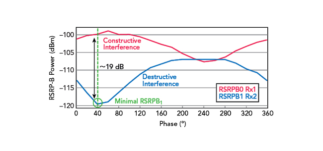
Figure 4 Commercial UE measurement in an anechoic chamber, showing RSRP-B power levels vs. calibration phase for one branch.
The calibration method implemented in the test system uses “intelligent” search algorithms to determine the channel parameters in the minimum time, which is crucial for cost-effective device verification. The approach and results confirms this method is an effective way to implement a quasi-connected testing environment with reproducible and defined channel conditions for throughput performance measurements and assessing performance under fading conditions.
CONCLUSION
Although 3GPP specifies crosstalk limits between virtual cables, it does not specify the calibration method to be used. Repositioning a DUT could, in principle, be used; in practice, however, this method would be too slow, not systematic and likely not possible with every DUT. The VCC method described and demonstrated in this article provides a systematic approach with fast convergence to determine the precoding calibration matrix parameters, which will be a crucial component for FR2 testing. For RRM measurements to assess handovers among multiple base stations, the method can be extended using a setup with multiple CATRs.5
As 6G research is aiming at frequencies beyond 100 GHz, the trend toward more integration of antennas will continue, requiring the same OTA testing. This same measurement approach can be extended to D-Band (i.e., 110 to 170 GHz) - one of the bands for 6G research.
ACKNOWLEDGMENT
The authors thank the following Rohde & Schwarz colleagues for fruitful discussions regarding the concepts and measurements: Jimson Eng and Oussema Harguem.
References
- 3GPP Technical Specification (TS) 38.521-4 Version 16.6.0 NR; User Equipment (UE) Conformance Specification; Radio Transmission and Reception 3rd Generation Partnership Project (3GPP), 3rd Generation Partnership Project (3GPP), 2020.
- Ibid, Appendix H.
- 3GPP Technical Specification (TS) 38.509 Version 15.9.0 5GS; Special Conformance Testing Functions for User Equipment (UE) 3rd Generation Partnership Project (3GPP), 3rd Generation Partnership Project (3GPP), 2020.
- R&S “5G New Radio: Fundamentals, Procedures, Testing Aspects,“ January 2021, Online: www.rohde-schwarz.com/5g-ebook.
- Corbett Rowell, Benoit Derat and Adrian Cardalda Garcia, “Design of a Multiple CATR System for Multiple Angles of Arrival Measurement of 5G mmWave Devices,” Microwave Journal, March 2021.