
Radar uses reflected radio waves to determine the range, angle or velocity of objects. These detection systems, which were once the exclusive domain of the aerospace and defense industry, are now gaining popularity in the consumer industry, most notably for automotive radar applications used in adaptive cruise control and autonomous driving assistance systems.1 The analog and RF hardware in modern frequency modulated continuous wave (FMCW) systems is considerably less complex than that of original pulse-Doppler radar, and commercial adoption is possible, in part, because of high volume semiconductor processes such as SiGe and CMOS technologies, which are enabling cost-effective systems for mass commercial applications.
This article presents a 60 GHz FMCW, frequency-division multiplexing (FDM), MIMO radar system for commercial radar applications.2 The unique architecture enables the total number of transmit (Tx) and receive (Rx) channels to be scaled by the number of ICs in the system, while still maintaining phase coherence between channels. The approach provides high frame-rate measurement, excellent phase stability and a large field of view (FoV). The radar architecture and ICs are designed so the system can be scaled to much larger radars.
The intended use for the radar system in this article is short-range, high-resolution detection of nearby moving objects when the radar itself might be moving, intended to capture the flow of people, drones and other autonomous systems. In addition, the system can support simultaneous localization and mapping, object detection (e.g., automobiles) and remote multi-target vital sign measurements for medical applications. FDM was determined to be the best choice to address the high-resolution requirements, where code division multiplexing was too complicated and the need for accurate tracking of fast-moving objects made time division multiplexing impractical. In addition, FDM allows accurate phase measurements, which supports medical applications such as remote monitoring of heartbeat and breathing rates from the detection of small movements of the chest.
60 GHz FMCW MIMO RADAR
Requirements for the radar system included fast imaging greater than 200 Hz, range resolution less than 5 cm, multi-target acquisition, moving target capability and high sensitivity to micromotion - all in a small, lightweight, low-cost footprint. The specifications for the system are:
- 1.5-degree angle resolution with 8 Tx – 8 Rx MIMO
- 3 to 5 cm range resolution
- 160-degree horizontal FoV
- 25-degree elevation FoV
The system offers a maximum detection range of 20 to 25 m for stationary human-size objects. Applying background subtraction, this range increases to 60 m for moving targets. The system also supports simultaneous detection of multiple moving objects without physically scanning the antenna. 3D systems with 160 x 160-degree FoV are also available.
While the radar system offers many potential use models, the multi-person vital sign extraction capability is interesting for future applications. For data analysis, the speed of the radar technology is key, as it can operate at 200 frames per second (FPS) when not supporting visual graphics and 50 to 100 FPS with visualization.
FMCW OPERATION

Figure 1 FMCW sawtooth waveforms.
A traditional pulsed radar detects the range to a target by emitting a short pulse and observing the time of flight of the returned target echo. This requires the radar to have high instantaneous transmit power and often results in a device with a large, expensive physical structure. FMCW radars achieve similar results using much smaller instantaneous transmit power and size by emitting a continuous microwave signal frequency modulated with a low frequency waveform, such as a sawtooth function with period T, whose duration is much greater than the return time of the echo (see Figure 1).
Unlike pulsed radar, FMCW systems transmit and receive simultaneously, eliminating the blind range that occurs when the receiver in a pulsed radar is turned off during transmission. FMCW systems can detect reflected signals from objects very close to the radar, enabling it to measure distances down to a few centimeters. The system achieves excellent range resolution, which is proportional to the reciprocal of the bandwidth, i.e., Δx = c/(2Δf), and high signal-to-noise ratio with narrow intermediate frequency (IF) bandwidth.
A simplified diagram of the system implemented in Cadence® AWR Design Environment®, specifically the AWR® Visual System Simulator™ (VSS) system design software, is shown in Figure 2. The signal source is divided between the Tx and Rx sides. Details of the Tx power amplifier (PA) and Rx low noise amplifier (LNA) chains - not shown in the figure - can be developed further. The Tx and Rx signal paths must be well isolated to operate properly, which impacts certain design aspects and limits the Tx power. Otherwise, power from the Tx side will leak into the Rx circuit, potentially saturating the LNA and/or down-conversion mixer.

Figure 2 Simplified FMCW radar in VSS. PA, LNA and individual MIMO channels not shown.
The simulation diagram illustrates the signal being radiated between the Tx and Rx antennas through a VSS radar target model that includes properties such as the RCS, distance, velocity and ambient conditions. The mixer will down-convert the signal reflected from the target, using the swept frequency from the voltage-controlled oscillator (VCO) as the local oscillator. Taking the difference of these two signals creates a beat signal directly proportional to the distance to the target. This IF is fed to an analog-to-digital converter (ADC) for signal processing, which extracts the target distance using a fast Fourier transform algorithm. Using multiple antennas, the Fourier transform also supports digital beamforming to produce a 2D image of the detected object.
Why FMCW MIMO?
The developers chose an FDM MIMO architecture to address the technical requirements for fast imaging and high-resolution of multiple targets. Using MIMO, the number of physical elements can be reduced significantly. For MIMO radar with Nt Tx elements and Nr Rx elements, there are Nt x Nr distinct propagation channels from the Tx array to the Rx array. Therefore, 64 virtual channels can be synthesized with only eight Rx and eight Tx channels, which greatly reduces system complexity, size and cost.
FDM transmits nonoverlapping frequencies simultaneously from each transmitter so different transmitter signals can be separated at the receiver.3 For this design, the frequency sweep, or chirp, was generated outside the Tx/Rx channels using a swept 10 GHz, phase-locked loop (PLL) signal generator feeding a 6x frequency multiplier. Direct digital synthesizers generated low frequency, in-phase and quadrature (I/Q) modulation signals with frequency offsets of 1 MHz for each individual Tx channel. External ADCs digitized the IF signals from the down-converted receive signals.
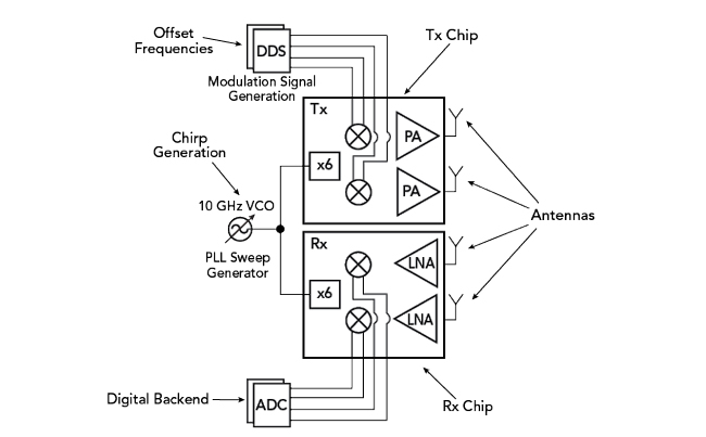
Figure 3 Conceptual system with two Rx and two Tx channels.
Since the FDM MIMO antennas transmit simultaneously, all Rx channels will receive all Tx channels separated by the constant frequency offset. The demodulator uses the original chirp frequency as a local oscillator (LO) to down-convert the frequency offset signals containing the frequency shift, resulting from the delay of the signals reflected off the targets. The Tx channels are separated at the digital back-end. While this approach can handle moving targets by measuring all the MIMO channels simultaneously, it requires modulators at each Tx for shifting the transmit frequency and faster ADCs, due to the wider IF signal bandwidth. Figure 3 is a conceptual system block diagram showing two Rx and two Tx channels.

Figure 4 FMCW MIMO radar block diagram.
SYSTEM DESIGN, VERIFICATION

Figure 5 Simulated down-converted signals.
VSS software was used to study the main system-level aspects of the MIMO radar. The software provides a block-level representation of the signal sources, LNAs, mixers, PAs, frequency multipliers, antennas and radar targets (see Figure 4), enabling the designers to tune and optimize the key parameters and incorporate real-world operation of the radar system as more circuit-level details were added. VSS software simulated the IF output at two of the Rx down-converter channels. Using the equation in Figure 1, the beat frequency (fb) was 300 kHz for a frequency sweep of 3 GHz bandwidth (BW) from 57 to 60 GHz, with a pulse duration (T) of 1 ms and target distance (r) of 15 m. The demodulated signal was the sum of fb and the offset frequency of each channel. Simulation of the Rx down-converted signal in Tx 1 (the green response in Figure 1) was 1 + 0.3 = 1.3 MHz, and the Rx down-converted signal in Tx 2 (the red response) was 2 + 0.3 = 2.3 MHz (see Figure 5).
RFIC Design and Analysis
The Tx and Rx RFICs are the core of the radar system. Each contains four channels in a very small area (see Figure 6), and additional ICs can be added to the system to increase the number of channels. It is advantageous for one RFIC to support multiple channels, to reduce assembly complexity and support scaling a system with a large number of channels. Separate Tx and Rx ICs enable independent Tx/Rx scaling, lower the leakage between Tx and Rx and support closer placement to the feed structure to reduce printed circuit board (PCB) losses. A single external VCO and PLL provide the LO signal that is distributed to all RFICs, resulting in excellent phase-noise correlation. A 10 GHz external signal is used for routing on the PCB, since routing a 60 GHz LO would be difficult in a system with many channels. This 9.75 to 10.25 GHz chirp is multiplied to the operating frequency of the RFICs.