Technical Feature
Characteristics of a Large Bandwidth Rectangular Microstrip-fed Inserted Triangular Patch in a Circular Slot Antenna
The characteristics of a rectangular microstrip-fed triangular patch in a circular slot antenna have been analyzed using the finite-difference time domain (FDTD) method. The impedance and bandwidth of the proposed antenna greatly depend on the design parameters. The normalized radiation resistance values of a triangular patch in a circular slot antenna varies less in the usable frequency band than for a square, or a circular patch. It means that the antenna shows a wider bandwidth than the other types, and although the use of a high relative permittivity ( er = 4.3) substrate usually restricts the operating bandwidth, the radiation resistance also has a low value. The measured bandwidth is approximately 96.3 percent for a SWR ≤ 2.0.
Yong-Woong Jang
Keukdong College
Chungbuk, Korea
Microstrip antennas offer the advantages of thin profile, light weight, low cost, conformability to a shaped surface and compatibility with integrated circuitry. The slot antenna has been investigated since at least the 1940s,1 and is treated in many electromagnetic text books.2,3 However, the major drawback of a microstrip antenna in its basic form is its inherently narrow bandwidth, which restricts its wide applications.
In the conventional microstrip-line fed slot antenna, a narrow rectangular slot is cut in the ground plane, and the slot is excited by a microstrip feed line either with a short4 or open5 termination. With this feed configuration, a good impedance match has been achieved for a narrow slot, and an impedance bandwidth of approximately 20 percent has been obtained.6 As the width of the slot is increased, the radiation resistance of the slot antenna increases proportionately as does the microstrip feed line. This, in turn, reduces the impedance bandwidth of the antenna even though the size of the slot is larger.7 Shum, et al.,8 have shown the possibility of increasing the bandwidth of the wide slot antenna by terminating the open end of the feedline within the width of the slot, but a substantial bandwidth improvement has not been achieved.
For the conventional ring slot antenna, a circular patch is inserted in the circular slot.9,10 In this article, a triangular patch inserted in a circular slot antenna is proposed, which has a similar radiation pattern but with a wider bandwidth than a ring slot9,10 or other patch antennas.11,12 The normalized radiation resistance values of a triangular patch in a circular slot antenna varies less in the usable frequency band than for a square, or a circular patch. It means that the antenna shows a wider bandwidth than for the other types. The SWR of a triangular patch in a circular slot antenna exhibits three resonances, in contrast to the ring slot or other patches. The multi-resonance is the cause of the broadbanding of the antenna. The feedline structure has a rectangular stub below the patch for broadband operation. The characteristics of a triangular patch in a circular slot antenna with a microstrip feed have been analyzed using FDTD. The proposed antenna shows a good impedance match over a wide frequency band. The SWR and input impedance were calculated by transforming the time domain results to the frequency domain. The optimal feed position for good impedance matching was determined through a full-wave analysis using the FDTD method. The proposed antenna was fabricated and measured using the optimized parameters.

Fig. 1 Structure and design parameters of the patch antenna.
FDTD Formulations
The FDTD method is formulated by discretizing Maxwell's curl equations over a finite volume and approximating the derivatives with central difference approximations. These finite-difference, time domain approximate equations contain a second-order error in both space and time steps. According to Yee's notation,13 in the FDTD cell, the space point is (iΔx, jΔy, kΔz), the time increment is nΔt and the arbitrary function is represented by F(iΔx, jΔy, kΔz, nΔt). In the analysis of the microstrip slot antenna design, Mur's absorbing boundary condition14 is applied. The calculated values obtained in the time domain by an FDTD method14-16 are then Fourier-transformed to obtain values in the frequency domain.
In order to calculate the input S-parameters for the antenna, a standard technique of time gating on the microstrip line to separate the incident and reflected waveforms is used. The ratios of the Fourier transforms of these waveforms give the S-parameters required. Since the microstrip feed line is an open stub, the microstrip antenna is a one-port circuit. Thus, the reflection coefficient S11 of the microstrip antenna is

where
V1 ref(t) = reflected voltage
V1 inc(t) = incident voltage
F = Fourier transform notation
From the calculated reflection coefficient, the SWR as a function of frequency can be calculated as

The bandwidth of the antenna was determined from the impedance data. Here, the term bandwidth will refer to the percent bandwidth unless otherwise specified. It is defined as

where
fr = resonance frequency
fr1 and fr2 are the frequencies at the edges of the bandwidth where the magnitude of the reflection coefficient is less than or equal to 1/3 (which corresponds to an SWR ≤ 2). The electric field in the far-field domain can be calculated as

where
k = propagation constant
Em = electric field at the slot
W = slot width
L = slot length
Antenna Structure and Simulation Results
Figure 1 shows the antenna structure which consists of the circular slot, the triangular patch radiator and a rectangular feed line, where Htp1, Htp2 are the lengths of the sides of the patch and Wtp is its width, Rcs is the radius of the circular slot, Lrf is the length of the rectangular feed line, Wrf is its width, Gsf is the distance between the slot center and the center of the rectangular feed line in the y direction and Wf is the width of the microstrip feed line. To analyze the antenna correctly, Δx and Δy are chosen so that an integral number of nodes fit within the feed line and the slot exactly. Δz is chosen so that an integral number of nodes fit the thickness h of the substrate exactly. The sizes of the space cells are Δx = 0.333 mm, Δy = 0.25 mm, Δz = 0.333 mm. The total analysis space is composed of 360 x 360 x 43 cells in the x, y and z directions, respectively. The dimensions of the antenna are set to Lrf = 64Δy, Wrf = 36Δx, Gsf = 40 Δy, Wf = 6Δx. The simulation is allowed to continue until the energy traveling back toward the source from the resonant cavity has subsided to a negligible level. Stopping the run early results in ripples in the calculated S-parameters. The performance of the antenna is sensitive to its design parameters (Htp1 , Htp2 , Wtp , Rcs , Lrf , Wrf , Gsf , Wf ).

Fig. 2 Normalized input impedance as a function of the feed line width; (a) resistance and (b) reactance.
Figure 2 shows the normalized impedance results when the width Wrf is varied from 8 to 16 mm and all the other parameters are fixed: Rcs = 26 mm, Lrf = 16 mm, Gsf = 10 mm and Wf = 1.94 mm. When Wrf is 12 mm, the normalized radiation resistance and reactance are about 1.0 and zero, respectively, at the center frequency of 3 GHz. It means that this antenna shows good impedance matching for Wrf = 12 mm at the center frequency = 3 GHz.
Figure 3 shows the normalized impedance when Gsf is varied between 6 and 12 mm while all the other parameters are fixed: Rcs = 26 mm, Lrf = 16 mm, Wrf = 12 mm and Wf = 1.94 mm. When Gsf is 8 mm, the normalized radiation resistance is about 1.7 at 3 GHz. But when Gsf is 10 mm, the normalized radiation resistance and reactance are about 1.0 and zero, respectively, at the center frequency. It means that the antenna is matched at 3 GHz when Gsf = 10 mm.

Fig. 3 Normalized input impedance as a function of the offset position; (a) resistance and (b) reactance.
Figure 4 shows the calculated SWR of the antenna as a function of Gsf , while all the other parameters are set to their fundamental values. When Gsf is equal to 6 mm, the bandwidth is approximately 0.15 GHz, when Gsf is 8 mm, the bandwidth is approximately 0.8 GHz, when Gsf is 10 mm, the bandwidth is approximately 2.8 GHz, and when Gsf is 12 mm, the bandwidth is approximately 0.9 GHz.

Fig. 4 Calculated SWR as a function of the offset position.
Figure 5 shows a comparison of the normalized impedance of a square, triangular and circular patch in a circular slot, with the following dimensions:
Square patch : Lsp = Wsp = 20 mm, Rcs = 26 mm, Lrf = 12 mm, Wrf = 16 mm, Gsf = 11 mm, Wf = 1.94 mm
Triangular patch : Htp1 = Htp2 = 26.5 mm, Rcs = 26 mm, Lrf = 12 mm, Wrf = 16 mm, Gsf = 10 mm, Wf = 1.94 mm
Circular patch : Rcp = 13 mm, Rcs = 26 mm, Lrf = 12 mm, Wrf = 16 mm, Gsf = 11 mm, Wf = 1.94 mm

Fig. 5 Comparison of the normalized impedance for a square, triangular and circular patch antenna's (a) radiation resistance and (b) radiation reactance.
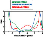
The normalized radiation resistance values for a triangular patch antenna change less in the usable frequency band than for a square, or a circular patch. It means that the triangular patch antenna offers a wider bandwidth than the other types. Figure 6 shows a comparison of the calculated SWR for a square, a triangular and a circular patch. The antenna design parameters are the same as before. The SWR of a triangular patch antenna in a circular slot is exhibiting the three-resonance characteristic, which can be contrasted with the ring slot or other patches. In this case, the multi-resonance is the cause of the antenna's broadband width.

Fig. 6 Comparison of the calculated SWR for a square, triangular and circular patch.
Experimental Results
The antenna was fabricated using an FR-4 substrate (er = 4.3, h = 1.0 mm) and the ground plane size of a two-element microstrip slot array antenna is 120 x 120 mm. The measurements were made on a HP8510 network analyzer.

Fig. 7 Measured SWR of the triangular patch antenna.
Although the use of a high relative permittivity (er = 4.3) substrate usually restricts the operating bandwidth, the experimental bandwidth is approximately 96.3 percent (1.811 to 4.702 GHz) for a SWR less than 2.0. The SWR as a function of frequency is shown in Figure 7 . The rectangular microstripline incorporated within the circular slot introduces a capacitance suppressing some of the inductance caused by the feed line, due to the thick substrate, and a dual resonance, near the resonance of the circular slot antenna, is created.

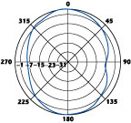
Fig. 8 Measured far-field radiation pattern in the x-z plane at f = 3 GHz.

Fig. 9 Measured far-field radiation pattern in the y-z plane at f = 3 GHz.
After calibration using a horn antenna, the far-field radiation pattern at 3.0 GHz was measured. Figure 8 shows the pattern in the x-z plane and Figure 9 in the y-z plane. The half-power beamwidth at 3.0 GHz in the x-z plane was 100° and 68° in the y-z plane.
The measured antenna gain vs. frequency is shown in Figure 10 . The gain is relatively high over most of the band, and is probably due to the effect of the finite size of the antenna substrate, that is, the power in the surface wave is not confined to the substrate but diffracted by the substrate edge, an effect which was not taken into account in the analysis. The measured gain is 2.5 dBi over the entire band, but drops off rapidly past the band edges. This is due to impedance mismatch and pattern degradation, as the back radiation level increases rapidly at these frequencies.

Fig. 10 Measured antenna gain.
Conclusion
The characteristics of a rectangular microstrip-fed triangular patch in a circular slot antenna were analyzed using the FDTD method. It was found that the bandwidth of the antenna greatly depends on the design parameters. The proposed antenna showed a low radiation resistance and a wide bandwidth of approximately 96.3 percent for SWR ≤ 2.0. This antenna should be useful as a broadband array antenna.
References
1. H.G. Booker, "Slot Aerials and Their Relation to Complementary Wire Aerials," Journal of the IEE (London) , Part IIIA, Vol. 93, 1946, pp. 620-626.
2. R.E. Collin, Antenna and Radiowave Propagation , McGraw-Hill, New York, NY 1985.
3. R. Garg, P. Bhartia, I. Bahl and A. Ittipiboon, Microstrip Design Handbook , Artech House Inc., Norwood, MA 2001, Chapter 7.
4. Y. Yoshimura, "A Microstrip Slot Antenna," IEEE Transactions on Microwave Theory and Techniques , Vol. 20, November 1972, pp. 760-762.
5. D.M. Pozar, "Reciprocity Method of Analysis for Printed Slot and Slot-coupled Microstrip Antennas," IEEE Transactions on Antennas and Propagation , Vol. AP-34, December 1986, pp. 1439-1446.
6. A. Axelrod, M. Kisliuk and J. Maoz, "Broadband Microstrip-fed Slot Radiator," Microwave Journal , Vol. 32, No. 6, June 1989, pp. 81-92.
7. M. Kahrizi, T.K. Sarkar and Z.H. Maricevic, "Analysis of a Wide Radiating Slot in the Ground Plane of a Microstrip Line," IEEE Transactions on Microwave Theory and Techniques , Vol. 41, January 1993, pp. 29-37.
8. S.M. Shum, K.F. Tong, X. Zhang and K.M. Luk, "FDTD Modeling of Microstrip-line-fed Wide-slot Antenna," Microwave Optical Technology Letters , Vol. 10, October 1995, pp. 118-120.
9. G. Dubost, "Large Bandwidth Circular Slot at Resonance with Directional Radiation," Electronics Letters , Vol. 24, No. 23, November 1988.
10. H. Tehrani, T.Y. Yun and K. Chang, "A Multi-frequency Microstrip-fed Shorted Square Ring Slot Line Antenna," IEEE Antennas and Propagation Society International Symposium , April 1999, pp. 920-923.
11. S. Bhusan Sharma, "Wideband Stacked SSFIP Patch Antenna for SAR Applications," Electronics Letters , Vol. 36, No. 11, May 2000.
12. Y.X. Guo, K.M. Luk and K.F. Lee, "Small Wideband Triangular Patch Antenna with an L-probe Feeding," Microwave Optical Technology Letters , Vol. 30, No. 3, August 2001.
13. K.S. Yee, "Numerical Solution of Initial Boundary-value Problems Involving Maxwell's Equations in Isotropic Media," IEEE Transactions on Antennas and Propagation , May 1966, Vol. 14, pp. 302-307.
14. G. Mur, "Absorbing Boundary Conditions for the Finite-difference Approximation of the Time Domain Electromagnetic-field Equation," IEEE Transactions on Electromagnetic Compatibility , Vol. 23, No. 4, November 1981, pp. 377-382.
15. D.M. Sheen, S.M. Ali, M.D. Abouzahra and J.A. Kong, "Application of Three-dimensional Finite-difference Time Domain Method to the Analysis of Planar Microstrip Circuits," IEEE Transactions on Microwave Theory and Techniques , Vol. 38, No. 7, July 1990, pp. 849-857.
16. A. Taflove and M.E. Brodwin, "Numerical Solution of Steady-state Electromagnetic Scattering Problems Using the Time-dependent Maxwell's Equations," IEEE Transactions on Microwave Theory and Techniques , Vol. 23, August 1975, pp. 623-630.
