
Return Loss
When an RF transformer’s output is connected to a perfectly matched load and a signal is induced at the input, there is invariably a reflected signal. The ratio of the reflected signal power to the input signal power is known as the return loss. This performance metric is useful in determining how strong the reflected signals will be from the input of the transformer, as some devices and circuits before the transformer in the signal chain may be susceptible to undesirable effects caused by those reflections.
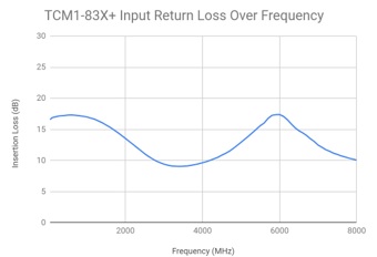
Figure 13: Average Input Return Loss of Mini-Circuits TCM1-83X+ RF Transformer
Amplitude Balance (Unbalance)
In the case of differential outputs of an RF transformer, the amplitude balance is the difference in magnitude of one differential output to the other. For many RF circuits, it is desirable to have signal power on balanced lines be as close to equal as possible in order to achieve fully-differential performance and reduce the amount of stray currents present in the signal path.
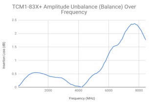
Figure 14: Average Amplitude Unbalance of a Mini-Circuits TCM1-83X+ RF Transformer
Phase Balance (Unbalance)
An RF transformer’s phase balance is a measure of how much phase difference there is between the device’s two differential outputs, referenced to 180 degrees. The length of the signal path through an RF transformer is a major factor in the phase of its output. Matching the signal path length between the two outputs is therefore critical in achieving good phase balance. An ideal RF balun transformer, for example, would have no difference between the amplitudes of its outputs, and the output signals would be exactly 180 degrees out of phase. In this case, the CMRR of an ideal balun would be infinite. Considering a real-world device would have some amplitude and phase imbalance. The CMRR is finite and a function of both phase and amplitude imbalance.
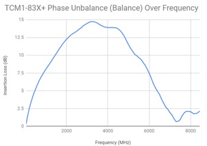
Figure 15: Average Phase Unbalance of a Mini-Circuits TCM1-83X+ RF Transformer
Common-Mode Rejection Ratio (CMRR)
The amount of attenuation common-mode signals incur from input to output when injected at the differential ports of a transformer (typically a balun) is known as the Common-Mode Rejection Ratio (CMRR). In some RF circuits, it is desirable to reduce the amount of common-mode signal from one node to another. In these cases, choosing an RF transformer (i.e. balun) with high CMRR can help to achieve this goal.
Max DC Current
If current beyond a certain threshold passes through an RF transformer, the magnetic field within the core may exceed the saturation tolerances, and the transformer may become saturated. In this state, the device suffers from degraded RF performance. There are methods to enhance the current carrying potential of RF transformers by using winding patterns to create opposing magnetic fields.
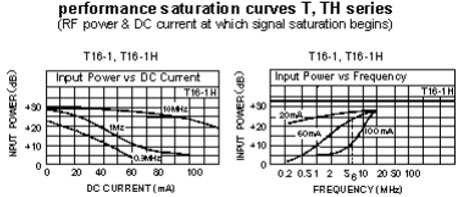
Figure 16: A plot of RF transformer saturation for DC current and RF input power
Max RF Power & Curie Temperature
Operating an RF transformer beyond the specified maximum RF power could lead to saturation of the core, increased insertion loss, and potentially even permanent damage through overheating. The Curie temperature of magnetic cores is the temperature at which the material’s magnetic properties degrade. Power and temperature ratings for RF transformers are typically determined in order to stay well below the Curie temperature. As the resistance of the conductive winding of a transformer is also a function of temperature, the maximum RF power threshold before overheating is a function of temperature and should be kept in mind when using RF transformers in extreme environments.
Operating Temperature
The way in which the operating temperature of an RF transformer is specified largely depends on the application. Typically, this metric is specified to avoid operation above or below the acceptable temperature range. As previously mentioned, RF transformers may suffer performance degradation and even permanent damage at some temperatures. This metric is important to understand, considering magnetic core transformers are highly sensitive to performance changes as a function of temperature.
Transformer Max Height
Many technologies of RF transformers are still hand-made or otherwise vary in physical tolerances, such as with core size, epoxy bonding, top hat thickness, etc. Therefore, a transformer’s maximum height provides a metric that can be used to ensure adequate clearance within an assembly or enclosure for these devices. As the max height specification is only based on the tallest feature in the case outline, the actual transformer height is generally smaller than the specification.
Conclusion
This concludes Part 3 of the Demystifying of RF Transformers Series on key RF transformer parameters. The last section, (Part 4) dives into methods for selecting RF transformers from a general perspective, and offers several application-specific recommendations.
References
- https://www.minicircuits.com/app/AN20-001.pdf
- https://www.minicircuits.com/app/AN20-002.pdf
- https://www.minicircuits.com/appdoc/TRAN14-2.html
- RF and Microwave Transformer Fundamentals featured in Microwave Products Digest 10-2009
- https://www.minicircuits.com/WebStore/Transformers.html