Core-and-Wire Baluns (Isolation & Autotransformer Baluns)
Isolation balun transformers are RF transformers with the unbalanced side tied to ground and the balanced side connected to the load. Similarly to standard RF transformers, the ratio of windings can also be used to create an impedance transformation. Figure 4 illustrates an autotransformer balun with balanced inputs at either end of the winding, a center tap to ground, and one end of the winding creating the unbalanced port. One major benefit of this type of transformer is that the input and output are electrically separated, allowing a degree of protection for systems that are prone to ground loops in their ground-level voltages.
Autotransformers have a different configuration from that of typical RF transformers, since this topology has only a single conductive path. Autotransformer baluns can be fabricated by winding a single wire around a ferrite core, or by cross-wiring the primary and secondary windings. A tap point between the two ends of the winding is used to access different voltage potentials respective to the transformer input voltage. This configuration incorporates a DC current path to ground for each terminal, dissipating any static build-up.
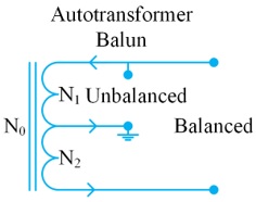 Figure 4: Diagram of an autotransformer balun.
|
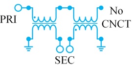 Figure 5: Diagram of a Marchand balun.
|
Transmission Line Baluns and Ununs
Transmission line balun transformers are typically constructed of a transmission line such as a coaxial cable wrapped around a ferrite core, and in some cases merely air. This 1:1 type of balun transformer creates a high choking reactance on the outer conductor of the coaxial cable, effectively reducing common-mode signals while allowing the internal currents of the coaxial transmission line to pass unimpeded (i.e. a Guanella Balun). Additionally, configurations include a bifilar capacitively coupled balun using two wires wrapped around each other as well as capacitively and magnetically coupled transmission lines wrapped around each other and then wrapped around a common core. The purpose of using a magnetic core with broadband transmission line couplers is to enable low frequency operation.
Broadband balun transformers are also constructed with various impedance transformations using several transmission lines in series and parallel arrangements. In this case, the impedance transformation is 1:n2, where n is the number of series-parallel transmission lines. Quarter-wave and half-wave transmission line balun transformers are also possible, although these types of baluns are best suited to applications with a narrow operating frequency range.
LTCC and MMIC Baluns
Balun production can also involve the use of planar metal structures with technologies such as LTCC and MMIC. This choice of design and fabrication is often proprietary. Generally, the main benefit of these designs is the small footprint that can be readily integrated into a microwave assembly. Unlike other baluns, LTCC- and MMIC-based baluns are produced using high-precision assembly machines and seminconductor manfacturing methods that yield much higher repeatability.
Key Balun Performance Parameters
Baluns share most of the same performance parameters as RF transformers, but the unique construction and use of baluns introduces additional considerations. These parameters include:
- Phase balance
- Amplitude balance
- Common-mode rejection ratio
- Balanced port isolation
- DC/ground isolation
- Group delay flatness
Phase & Amplitude Balance
Phase and amplitude balance (or unbalance) are a measure of how equal and opposite a balun’s balanced output voltage and current are. In essence, any unbalance in a balanced line’s voltage/current phase or amplitude yields additional losses and stray currents. Phase balance measures how closely the phase difference between the inverted input and non-inverted input are to an ideal 180° out of phase. The amplitude balance is the absolute value of the output power on each balanced line. For these parameters, each balanced line should be as close to equal as possible. The determining factors for phase and amplitude balance in real baluns include material properties, fabrication methods, and match between the output lines. Modern high-performance baluns are generally specified for no more than a few degrees of phase unbalance and a few dB of amplitude unbalance.
Common-Mode Rejection Ratio
The Common-Mode Rejection Ratio (CMRR) is a measure of how well common-mode signals are attenuated from the balanced port to the unbalanced port. This ratio is dependent on amplitude and phase unbalance. A balun with better amplitude and phase balance will also exhibit enhanced CMRR. A generally accepted guideline is that a 0.1 dB improvement in amplitude balance, or a 1 degree improvement in phase balance, will enhance the CMRR of a balun by roughly 1 dB.
Balanced Port Isolation & DC/Ground Isolation
Balanced port isolation is a measure of the ratio of input signal strength to output signal strength from one balanced port to another (insertion loss). More often than not, this parameter is not very high in most balun designs. DC isolation is a measure of the DC conductivity between the unbalanced port and balanced ports while ground isolation is a measure of the isolation between the unbalanced port ground and the ground (or pseudo ground) of the balanced ports. These isolation figures are important to determine a device’s immunity to noise and interference. The isolation potential of a balun is often limited by the balun topology.
Group Delay Flatness
Group delay is the time it takes for the frequency components of a signal to pass through a device. The flatness of the group delay is a way to gauge the amount of distortion the broadband or high-speed signals will encounter passing through a device. It is generally desirable for every frequency component of a signal to pass simultaneously. In the case of a balun, good broadband matching is related to good group delay performance. Baluns with better return loss will typically demonstrate better group delay flatness.
Important Balun & Unun Applications
Baluns were originally used to provide impedance matching and to present balanced outputs to balanced antennas fed by unbalanced transmission lines. With the advent of solid state electronics, the outputs and inputs of many solid state devices (e.g.amplifiers, mixers, DACs/ADCs) present unbalanced ports. Though unbalanced outputs can readily be connected to common transmission lines such as coaxial cables, differential signaling lines are generally less susceptible to noise and crosstalk. Many of these lines are also less expensive than coaxial cables for long distance transmission.
For example, balancing push-pull amplifiers and mixers enables designs with reduced spurious content and enhanced CMRR, i.e. double-balanced mixers (see Figures 6 and 7). Note that the center taps on the baluns in Figure 7 are used for biasing the balanced amplifier. Another common application is the balancing and impedance matching of wideband converters to unbalanced sources, which generally exhibit port impedances that are very different from those of converter ports (see Figure 8).
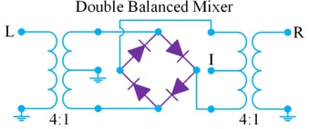
Figure 6: Double-balanced mixer using baluns on the input and output.
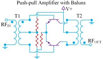
Figure 7:Balanced amplifier with baluns on the input and output.
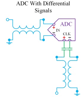
Figure 8: An ADC with differential input transformed into single-ended output.
Conclusion
Baluns have become highly useful devices that address many challenges of RF/microwave systems, transitioning unbalanced circuits (single-ended or ground referenced) to balanced circuits (full differential). Baluns also provide impedance matching between these circuits and enhance the CMRR of interconnect and devices. Baluns can be fabricated using a variety of technologies, including core-and-wire transformers, transmission line transformers, even low-profile, small-footprint LTCC and MMIC technologies.
References
1. Understanding, Building, and Using Baluns and Ununs, CQ Communications, 2003 by Jerry Sevick W2FMI
2. More on the 1:1 Balun, Jerry Sevick
6. RF and Microwave Transformer Fundamentals featured in Microwave Products Digest 10-2009
