Technical Feature
Design of a Predistortive High Power Amplifier Using Carrier Complex Power Series Analysis
In this article, a new carrier complex power series for linearizing the distortion effects of a high power amplifier (HPA) is proposed. The amplitude (AM-to-AM) and phase (AM-to-PM) nonlinear characteristics of the HPA are combined to generate a carrier complex power series. An inverse carrier complex power series for a predistortor is also proposed. An HPA in the IMT-2000 band was fabricated with a measured gain and P1dB of 34.06 dB and 35.4 dBm, respectively. By using the proposed power series, the carrier-to-intermodulation ratio (C/I) of the HPA is improved by 17.01 dB at an output power of 25.43 dBm per tone with two-tone frequencies at 2.1375 and 2.1425 GHz.
Yong-Chae Jeong
Chonbuk National University
Chonju, Korea
Sang-Young Yun
Sewon Teletech Inc.
Kyeonggi-Do, Korea
In a mobile communication or satellite communication system, the HPA amplifies the carrier signals and feeds them to the antenna. In a weak nonlinear amplifier, the input and output voltages can be expressed using a power series. If the input signals consist of two, equal-amplitude, in-band RF signals, whose frequency spacing is much smaller than their RF frequency, many distortion signals occur besides the amplified input signals at the output port. It is very difficult to eliminate the distortion signals located close to the amplified input signals. Particularly, in a communication system that has several transmitting channels, the distortion signals can interfere with adjacent channels. There are several methods for reducing distortion signals, including input power level back-off, feedforward, feedback and predistortion.1 In this article, a carrier complex power series, including the AM-to-AM and AM-to-PM nonlinear characteristics of the HPA, is proposed, as well as an inverse carrier complex power series for a predistortor to linearize the HPA.

Fig. 1 Complex domain gain characteristics.
Carrier Complex Power Series Analysis
In general, an HPA is not a linear device, and its output signals are not linearly scaled input signals. Consider the amplifier as a two-port network, which can be modeled by a power series. If the two-port network is memoryless, the output voltage can be represented by a power series of the input voltage as
v0 = k1 vi + k2 vi 2 + k3 vi 3 + … (1)
The coefficients ki in Equation 1 are real numbers and Equation 1 is obtained from the amplitude distortion in (AM-to-AM) of the HPA.
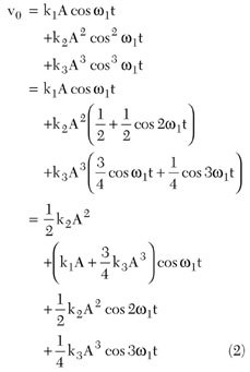
The nonlinear gain at the fundamental frequency component is

The above equations are derived from the AM-to-AM characteristics of the HPA, so they cannot explain the AM-to-PM characteristics.2
If a power series can represent both amplitude and phase distortion characteristics of an HPA, the linearization method can be made much simpler.3 In this article, a simplified carrier complex power series in which complex coefficients represent the amplitude and phase distortion characteristics of an HPA is derived.
To justify this approach, an IMT-2000 band HPA was designed, and its AM-to-AM and AM-to-PM characteristics were obtained using a CW power sweep. Consider a single, unmodulated CW carrier as the input signal which has the form
vi = Acos( w1 t + q) Þ vis = Aej q = A L q (4)
where
A = amplitude
w1 = radian frequency
q = phase
The input signal can be expressed in phasor or exponential form. The output signal is a single, unmodulated, CW carrier of the form
vo = A· cos( w1 t + q·) Þ vos = A·ej q· = A· L q· (5)
where
· = output quantities
Equation 6 shows the proposed carrier complex power series for the HPA where fi are complex numbers. In the case of a weak nonlinearity, the output voltage can be represented by the first two or three terms. Only odd-order terms of the carrier complex power series are considered.

The output signal can be represented in the complex signal domain as shown in Figure 1 . The input signal is shown on the real axis. The f1 of Equation 6 is the complex linear gain which combines a fixed gain and a phase shift. Thus, the first coefficient of the carrier complex power series is obtained from the small input signal power level as

When the output power level is operated at the 1 dB compression point (P1dB ), the input signal can be written as vis-1dB = A1dB ej q1dB . Then the ideal linear complex output signal is defined as
vos = f1 vis-1dB = f1 A1dB ej q1dB (8)
Assuming that the real output signal is vos-1dB = A·1dB ej q·1dB , the relationship between vos and vos-1dB is defined as

where vos-1dB (amplitude A·1dB and phase q·1dB ) is the output signal at the 1dB compression point. The 1dB compression point is the point where the amplifier gain is lower by 1dB, compared to its value in the linear region. Around the 1dB compression point, the relation between the input and output signals can be obtained from Equations 3 and 9.
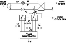
Fig. 2 Block diagram and operation of the proposed predistorted HPA.
Therefore, the simplified carrier complex power series is written as
vos = f1 vis + f3 v3 is (11)
In this article, a predistortion type linearizer is proposed, of which the transfer function is characterized by the inverse carrier complex series. Figure 2 shows the block diagram and the proposed predistortion linearizer mechanism.4 Assuming that the inverse carrier complex power series is given by Equation 10, it represents the transfer function to linearize the HPA.
vis = a1 vin + a3 v3 in (12)
If Equation 12 is substituted into Equation 11, then the overall transfer function can be shown to be
vos = f1 a1 vin + (f1 a3 + f3 a3 in ) v3 in + 3f3 a2 1 a3 3 v5 in + 3f3 a1 a3 3 v7 in + f3 a4 4 v9 in (13)
If the gain of the predistorter is set to 0 dB at a low power level, the complex linear gain of the inverse signal is defined as

If the predistorted HPA has a linear complex gain, the third term of Equation 13 is zero.

The inverse carrier complex power series of the predistorter, using the carrier complex power series, has the form

The third term is obtained from the carrier complex power series of the HPA. Thus, the inverse carrier complex power series of the predistortor depends on the carrier complex power series of the HPA.

Fig. 3 HPA frequency characteristics.
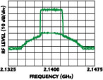
Fig. 4 CW power sweep characteristics of the HPA.
Simuation and Experiments
A 3.5 W power amplifier module was implemented with an AH1 from Watkins-Johnson and FLL171ME, FLL105MK from Fujitsu. Figure 3 shows the gain characteristics of the HPA using a frequency sweep. Figure 4 shows the nonlinear characteristics of the HPA using a CW power sweep. The measured gain is 34.6 ±0.1 dB and the measured P1dB is 35.4 dBm. The nonlinear output results of the modeled HPA using a fast Fourier transform (FFT) are shown in Figure 5 , and from it the distortion effect of the nonlinear HPA for two-tone or multi-tone signals can be predicted.

Fig. 5 Simulation results for the modeled HPA using FET.
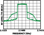
Fig. 6 Circuit diagram of the inverse signal generator.
The diode used in the designed inverse signal generator (ISG) is an HSMS-2852 from HP; the 3 dB hybrid coupler is a JX503 from Anaren. Figure 6 shows the detailed circuit diagram of the ISG. Figure 7 shows the calculated and measured inverse carrier complex power series characteristics.

Fig. 7 Calculated and measured characteristics of the inverse signal (a) gain and (b) phase.
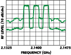
Fig. 8 CW power sweep characteristics of the HPA with predistorter.
To confirm the improvement, a CW power sweep and a two-tone test were performed. Figure 8 shows the CW power sweep characteristics of the HPA with predistortor. When compared with the same characteristics without the predistortor, the variation of gain and phase is much decreased. Figures 9 and 10 show the two-tone output characteristics of the HPA with and without predistortor. The two-tone frequencies are 2.1375 and 2.1425 GHz. When the output power level is 25.43 dBm per tone, the improvement is about 17 dB. Figure 11 shows the improvement by comparing the intermodulation distortion characteristics of HPA with and without predistortor when the output level changes from 21.43 dBm per tone to 28.43 dBm per tone; the improvement of C/I is approximately 13.34 dB.

Fig. 9 The output characteristics of the HPA without predistortor. (Pout = 25.43 dBm/tone)

Fig. 10 The output characteristics of the HPA with predistortor. (Pout = 25.43 dBm/tone)

Fig. 11 Characteristic improvements in C/I caused by the predistortor.
Conclusion
In this article, a carrier complex power series, including amplitude (AM-to-AM) and phase (AM-to-PM) nonlinear characteristics of the HPA, is proposed and the inverse carrier complex power series of a predistortor using the proposed carrier complex power series is also introduced. With these series, the C/I of a 3.5 W HPA in the IMT-2000 band is improved by approximately 13 dB. If the coefficients of the power series can be derived to an order greater than three, the performance of the linearizier could be obviously improved.
References
1. P.B. Kennington, High Linearity RF Amplifier Design , Artech House Inc., Norwood, MA 2000.
2. T.T. Ha, Solid-state Microwave Amplifier Design , John Wiley & Sons, New York, NY 1981, pp. 202-246.
3. S.W. Chen, "Effects of Nonlinear Disortion on CDMA Communication Systems," IEEE Transactions on Microwave Theory and Techniques , Vol. 44., No. 12, December 1996, pp. 2743-2750.
4. W.W. Lee, Y.C. Jeong, K.L. Park, S.W. Yun and I.S. Chang, "Design of Predistortion Linearizer Using Diodes," Proceedings of KEES , Vol. 15, No. 2, 1992, pp. 141-143.
Yong-Chae Jeong received his BSEE and MSEE degrees in electronics engineering from Sogang University, Seoul, South Korea, in 1989 and 1991, respectively, and his PhD in electronics engineering from Sogang University in 1996. From 1991 to 1998, he worked as a senior engineer with Samsung Electronics. In 1998, he joined both the division of electronics and information engineering and the Institute of Information and Communication at Chonbuk National University, Chonju, South Korea. He is currently an associate professor teaching and conducting research in the area of microwave devices and base station amplifiers.
Sang-Young Yun received his BSEE degree in electronics engineering from Howon University, Kunsan, South Korea, in 1998. In 2001, he received his MSEE degree in information and communication engineering from Chonbuk National University, Chonju, South Korea. He has been working for Sewon Teletech Inc. since February of 2001, where he develops high power amplifiers.
