
SIMULATION ENABLED ML
In the Ansys ML approach, they follow a three-step process to generate data, train the ML algorithm and then run detection on scenarios and compare with ground truth. Figure 4 illustrates the automated process to generate the data. They first create the radar scene by combining library components to generate full scenario with velocity and location randomly placed within environment limits. Automated results are generated as range-Doppler returns for a radar module, and fully annotated range-Doppler plots are produced using an XML file with locations and object identifiers.
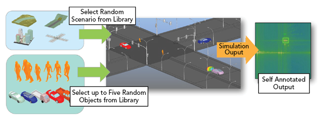
Figure 4 Radar scenario is built by placing components from a library for stationary and moving objects. Simulations result in range-Doppler plot with self-annotation.
For the training, they implemented a deep learning model based on a YOLO v3 architecture, a convolutional neural network-based approach used in many image-based object detection classifiers and trained from scratch using radar results obtained from physics-based simulation. Figure 5 illustrates the overall neural network training using labeled data that may include upwards of 9,000 scenarios. The software then proceeds to test and validate the model by testing against a new radar scenario that was not used during the training. Ansys found an 83 percent mean average precision (mAP), a metric used to quantify accuracy of object detection. Pedestrian detection accuracy improvement was observed with more training data, increasing from 61 percent to 74 percent, when using 3,000 to 9,000 training scenarios, respectively.
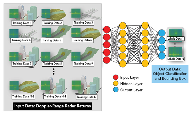
Figure 5 Multiple scenarios are used to train a neural network which can then provide inference for object classification.
Ansys attempted an extremely complex radar scenario that also included a concrete road structure, not included as part of the training, and a very tight three vehicle cluster (see Figure 6). The mAP of this scenario was a lower 52 percent, with a false positive detection of an automobile at the concrete road structure and an inability to isolate one of the three closely spaced vehicles.
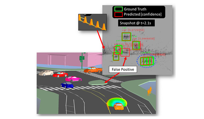
Figure 6 Highly complex radar scenario used for validation.
Ansys has shown that it is possible and desirable to leverage physics-based simulation to train ML algorithms for automotive radar applications. Ansys HFSS SBR+ was used for dataset generation with up to 9,000 unique scenario simulations. Each scenario requires one to two GB of RAM, with an average solve time of 20 minutes using a single core. The method is parallel with near linear scaling with compute cores. 6,000 scenarios can be computed in half a day on a 128-core machine. Results show that objects can be located and classified in a real-world environment with good confidence.
Cadence AWR Uses Machine Learning to Accelerate Designs
Cadence AWR, San Jose, Calif.
Today’s RF systems are largely developed with software tools that provide engineering teams with ready access to compact and electromagnetic (EM)-based models, as well as to a broad range of simulation and optimization technologies that address all stages of electronic product computer-based design. Yet, as each new, next generation of electronic systems grows more complex, design work and fabrication likewise grow more challenging and expensive. There is real concern that engineering and economic hurdles threaten the pace of the More than Moore (MtM) law for the development of microelectronics and for non-digital functions such as RF to mmWave front ends and the integration of multi-fabric technologies.
ML, AI and cloud computing (CC) are all avenues being explored to help to mitigate these concerns. Performing various engineering tasks through learned decision making and optimized design flows for greater productivity, as well as enhanced speed/capacity of simulation technologies, are a few examples where ML, AI and CC are being employed. In general, convolution and recurrent neural networks along with machine and deep learning algorithms will be significant drivers in the development of 5G communication systems and beyond. These systems include RF through mmWave electronics and the electronic components within them. As such, decision making design automation will be essential to the development of future communication and wireless detection systems.
Cadence® AWR Design Environment® software uses genetic optimization algorithms to explore a greater range of design candidates for wireless product development by applying ML to accelerate the design of antennas, filters and impedance matching networks, all key components within 5G wireless communication and radar systems. The software operates from performance criteria set by the designer and is enhanced by the designer’s knowledge in defining the goals/search limits, after which the tool assumes the task of empirical topology/parameter design space optimization.
NETWORK SYNTHESIS
The AWR Design Environment network synthesis wizard creates optimized two-port matching networks composed of discrete and distributed components using ML and AI (see Figure 7). The designer specifies the maximum number of sections and the types of components to include in the search space and the wizard explores for the best circuit topologies and optimizes the component parameter values.
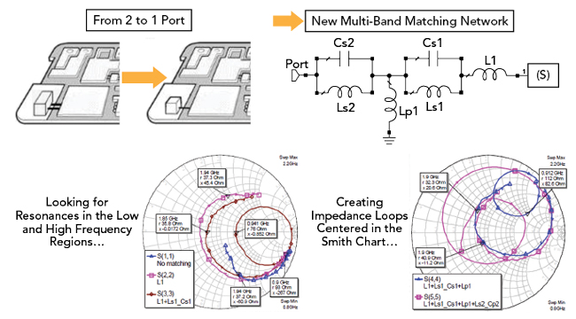
Figure 7 Multi-band impedance-matching circuits with minimal components (six-element case shown) using the AWR Design Environment network synthesis wizard to support antenna integration (Source: Fractus Antennas).
The wizard’s optimization goals are specified by the designer using a dedicated set of synthesis measurements, much like optimization goals are normally defined within AWR software. Specialized measurements are provided for input noise matching, amplifier output power matching and inter-stage matching. The optimum reflection coefficients are specified over frequency and can be provided in the form of load pull data, network parameter data files or even circuit schematics.
When generating possible network topologies, the wizard begins by creating all the possible topologies for a single component. The number of such topologies is generally equal to the number of checked boxes on the software’s components page. For example, to create a two-section topology, the wizard takes each one-section topology and goes through the list of components allowed to follow the first one. The process repeats, producing an exponential growth in the number of topologies as a function of the number of sections. This setting, which is referred to as “M” and has a default of 1,000, provides a way to constrain the exponential growth by limiting the number of N-section topologies that will be used to create the topologies with N+1 sections. Only the “M” best topologies will be propagated.
This search-based method determines candidate circuit topologies based upon user specification of capacitor, inductor and transmission line element types to be used in series and shunt slots. The wizard then performs an exhaustive search, exploring all possible topologies by expanding the solution up to a user-defined maximum number of sections.
Heuristic methods then determine what element can follow an existing element. Through a self-learning (or ML) process, the synthesizer understands which elements can be placed serially, such as two different width transmission lines to form a stepped-impedance transformer or a fully distributed transmission line network for higher frequencies. It also understands what cannot be placed serially, such as two capacitors from a matching perspective.
In addition to network synthesis, AWR software products also employ evolutionary algorithms to create novel antenna structures in which AI employs genetic optimization and EM analysis for exploration of designs. Whether designers are focused on developing impedance matching networks for broadband amplifiers or next generation antenna design, AWR software capitalizes on advances offered by ML, AI and CC. The ability to support different classes of design, as well as simulation technologies, with a variety of such computational techniques will become more and more critical to the future of RF to mmWave design and preserve MtM.
Keysight’s AI/Machine Learning Optimizations in Design Software
Keysight Technologies,
Santa Rosa, Calif.
Keysight Technologies has a long history in AI/ML research as well as applying AI/ML techniques in modeling, simulation and test environments. Keysight Labs and application teams conduct this research, often partnering with select universities and individual researchers on specific exploration opportunities. Keysight is well known for the successful adoption of AI/ML techniques in simulation and modeling of field effect transistors using neural networks and in inference engines for manufacturing analytics and test plan optimization.
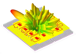
Figure 8 Antenna array far field gain pattern from 16 array elements (Source: Global Foundries and Fraunhofer IIS/EAS/IZM).
Keysight’s focus when combining AI/ML techniques with EM simulation is finding improved solutions to optimization and EM design problems. For example, a traditional application of AI/ML techniques is searching for an optimal antenna shape within a set of physical constraints imposed by cost or available area (see Figure 8).
To create an optimal antenna, designers start by selecting a base design described by a large set of parameters with a wide range of values. The effect of those parameters, or their combination, is typically hard to predict or model. Sweeping through the entire parameter space and selecting the best configuration is not practical. Each new configuration also requires an EM simulation that can take a significant amount of time to complete. Any technique that reduces the number of EM simulations will have a large impact on the time it takes to produce the optimal antenna.
Traditional optimization techniques frequently produce unsatisfactory results as they tend to become stuck in local optima. Using evolutionary algorithms to search the continuous design parameter space enables both limitation of the number of EM simulations needed and avoidance of local minima in an efficient way.
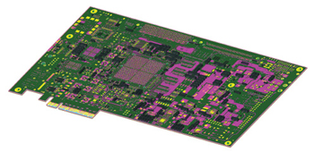
Figure 9 A Xilinx Kintex UltraScale FPGA Evaluation PCB showing AI/ML-aided decap placements.
Keysight has also had success in application of AI/ML techniques to EM simulation for finding the optimal number of decoupling capacitors (decaps) needed on a PCB for power delivery from the voltage regulator to the chips. Power distribution networks require placement of decaps between power and ground rails. Determining the optimal number of decaps is key to PCB performance and reducing costs. For a complex PCB, there can easily be 100 decap placements and for each of them a wide set of available choices. Sequencing through all possible combinations to find the optimal number of decaps is again impractical, and would take hundreds of years, even taking advantage of parallel simulations (see Figure 9).
Given a choice between five decap models for each location, the number of combinations is 6,100, including the option not to place one. Deciding against decap placement is a valid choice as it reduces PCB cost. Keysight looked at how experts in the field approached the decap problem and combined it with AI/ML techniques that reduce search spaces. The AI/ML algorithm quickly dismisses areas in the parameter space that are unlikely to yield a good solution. It uses the techniques of experts to find solutions in areas that stand a good chance to provide a solution. The algorithm accelerates each evaluation of a potential solution by precomputing the EM part of the problem, so that it leverages a previous solution efficiently and does not require starting the EM simulation from the beginning.
MathWorks Seamlessly Integrates AI into Their Tools
MathWorks, Natick, Mass.
MathWorks has a range of tools built on MATLAB and Simulink that are widely used to model, simulate and deploy wireless and radar systems. Tools such as Antenna Toolbox, RF Toolbox, Phased Array System Toolbox and Sensor Fusion and Tracking Toolbox span across the RF, antenna, phased array, signal processing and data processing disciplines. Modeling building blocks, algorithms and system simulators are also available in standards-based toolboxes including 5G Toolbox, LTE Toolbox and WLAN Toolbox.
MATLAB supports a broad range of AI algorithms and training workflows for deep learning, ML and reinforcement learning. These are part of the integrated environment that includes their wireless and radar tools including Communications Toolbox and Phased Array System Toolbox, enabling system designers to apply these AI techniques directly in their applications. This could include labeling baseband data to train a network for supervised learning. Modulation ID and target classification are good examples of this type of supervised learning. In other applications, AI techniques are used to improve the performance of the system. For example, a wireless system may learn how channels vary over time or how to perform optimally in the presence of interference.
5G wireless systems and multifunction radar systems operate in such complex environments and perform tasks that previous generation systems never had to address. There are many system-level challenges that are hard to solve. AI can be applied to these systems to solve problems and improve system performance. The good news is that a lot of the foundation for AI that evolved for vision-based systems can be leveraged. Algorithms and workflows specific to signals are also available to make AI possible for RF applications. System engineers can now integrate AI into their workflow seamlessly using MATLAB and Simulink and supporting toolboxes.
In wireless and radar applications, this spans the following steps in system design workflows (see Figure 10):
- Connecting to radios and radars directly
- Managing large data sets including the process of labeling baseband signals (with Signal Processing Toolbox)
- Extracting features from signals to use with ML networks (with Signal Processing Toolbox and Wavelet Toolbox)
- Synthesizing realistic data to train deep learning networks
- Designing AI networks that are specific to wireless and radar applications (with Deep Learning Toolbox)
- Connecting to networks in the larger AI ecosystem (with Deep Learning Toolbox)
- Deploying code to a processor, GPU or FPGA
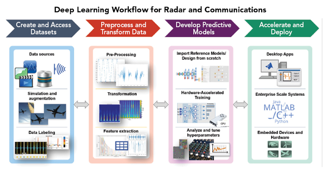
Figure 10 MathWorks tools span the AI workflow for radar and wireless communications from data acquisition to deployment.
The workflow spans from the earliest prototyping stage to deployment which ensures that the systems that get delivered match the system models built at the earliest project phases. System engineers can generate great amounts of data using channel models, impairments and environmental conditions in system simulations. Having this data can reduce the amount of field testing required to train a deep learning network. Even when data exists, data synthesis can be invaluable to augment data with corner case conditions. This helps to ensure system developers deliver more robust systems. Robustness in this case translates to better results in areas such as improved classification or better target recognition. This could also mean higher performance in the presence of interference or recognizing trusted RF sources.
The most common AI applications in wireless and radar include areas like modulation identification, spectrum management, channel estimation and target classification. An RF fingerprinting application example that MathWorks recently modeled was delivered with the R2020a release. This is an example that was widely requested by their customers and is especially interesting for cyber security applications. The idea is that a network can be trained to recognize an RF fingerprint between a trusted transmitter and receiver. If spoofing is attempted to interfere with operations or to gain unauthorized connections, the trained AI network can recognize this condition. Using Communications Toolbox and WLAN Toolbox, MathWorks developed the algorithms and trained the AI system with purely synthesized data. They were then able to obtain the same results when they tested the system with data collected with off-the-shelf radios (see Figure 11).
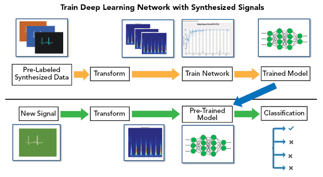
Figure 11 Train AI networks with synthesized radar or wireless data and test with real-world data.
OVERALL SUMMARY
AI and ML have been implemented into many EDA tools and platforms to automate many design processes and obtain results faster and more accurately as shown by Altair, Ansys, Cadence AWR, Keysight and MathWorks. They have also enabled the simulation of scenarios that were previously too complex or data intensive to execute without AI and ML. The implementation of these capabilities is only just beginning and expect many new improvements in the near future with AI and ML.