

Higher levels of integration have also yielded improvements in measurement technology. All calibration data is on the sensor, making it straightforward to move sensors from one host to another without concerns about applying appropriate correction factors.
Today, most power sensors have cable interfaces enabling direct connection to a LAN. Many also have simple, standard USB interfaces, enabling connections to PCs, laptops or other test and measurement equipment, such as a signal generators and spectrum analyzers (see Figure 3). Some sensors have both interfaces.
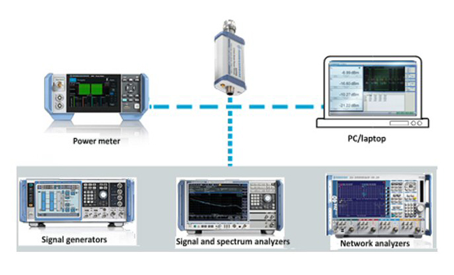
Figure 3 Modern power sensors can connect with various devices via a USB interface.
FLEXIBILITY AND NEW USE CASES
Options for controlling power sensors have improved significantly because of their ability to function as standalone measurement devices. While the traditional power meter configuration still provides value, USB and LAN interfaces offer new flexibility.
Having measurement and processing power onboard the sensor also enables faster measurement speeds. With onboard buffer memory, today’s sensors eliminate the constant communication with the host device. They can make up to 50,000 measurements per second, storing the results in buffer memory for bulk transport to their host devices. Spending more time measuring and less time communicating improves the accuracy and speed of the measurement.
In the Lab
When working with test equipment in a lab, there are a several ways to use a power sensor. For infrequent, simple power measurements, which may be done ad-hoc, the power sensor can leverage its USB interface and to use another instrument, such as a signal generator or spectrum analyzer, as a host device.
With some products available today, the host instrument opens a pop-up window, enabling the sensor to be controlled from the front panel of the instrument, which also displays the results. This approach is ideal for simple, infrequent measurements. Sensors can easily be connected when required, saving the bench space of a separate power meter.
The power sensor can also be connected to a laptop or PC using the USB port. With free software, which most test equipment manufacturers provide, the power sensor can easily be controlled from a laptop.
When power measurements are complex or frequent, a power meter is an essential instrument. Since its sole purpose is controlling the power sensors and displaying results, the power meter adds many capabilities, such as high-resolution touchscreen displays for setting up measurements and displaying results quickly and easily. Setting up pulse or gated measurements is much easier than using another instrument, and the power meter has a dedicated display to view results.
The power meter excels when multiple power sensors are used, as it provides a single instrument for connecting and controlling all the sensors, with a single point to trigger all sensors simultaneously. For complex setups, this removes a source of timing error. When analyzing data, the power meter can differentiate inputs from the different sensors, calculating parameters such as gain.
Automated Test Systems
When selecting equipment to be used in automatic test equipment (ATE), the core RF requirements must first be met. Beyond this are requirements that must be considered, including measurement speed, complexity and cost to the system computer interface. Fast measurements are possible by leveraging modern power sensors with onboard buffer memory. The issue is how to control the sensors and access the data.
What is the best interface: LAN, USB or the general-purpose interface bus (GPIB)? To the power sensor, it does not matter, as all three can be used without affecting measurement time or RF performance; no matter what interface is used to control the test system, the power sensors can be integrated.
Many legacy systems use the GPIB interface. When equipment is upgraded, using the GPIB interface minimizes changes and, therefore, risk. Many modern power meters offer a GPIB interface to enable the latest sensor technology to be added to these legacy systems. To ease the transition from an older power measurement platform, newer power meters also offer code emulation. This is a feature where, from a programming perspective, a new power meter can be seamlessly dropped into an existing system. It will respond to all the programming commands written for the old power meter, which enables the hardware to be upgraded without having to update production test code. This saves time and money, while reducing risk.
When building a new ATE station, Ethernet is the most common control interface. Until recently, this meant using a power meter since it had an Ethernet connection. While this is practical when the system calls for a complex measurement setup that benefits from the capabilities of the base power meter - such as multi-sensor control or ease of triggering - in some cases base units were only used to provide an Ethernet connection. Now a wide range of power sensors have Ethernet ports, able to be controlled directly without the base unit. This capability reduces system cost and complexity by removing the power meter.
Remote Locations
The development of a complete range of networking sensors significantly changes the operating environment for sensors deployed in a remote environment. One example is monitoring the RF power of a satellite system at a remote ground station. This same situation applies to any remote RF transmission system or network, where the system is based at a remote location and the power sensors are placed at several measurement points. Without a LAN, the sensors must be connected to a power meter or PC, with the limitation that the sensor and power meter or PC must typically be within 10 feet to use a USB interface. With the LAN interface, the sensors can be placed wherever needed and accessed directly by the control center or other locations, eliminating the need for additional equipment at the remote site.
Some sensors with LAN interfaces have built-in web servers enabling real-time monitoring anywhere in the world (see Figure 4). This makes monitoring and troubleshooting of RF systems in remote locations much simpler and more efficient.

Figure 4 Power sensors with integrated web servers can be monitored and controlled via the internet.
CONCLUSION
The flexibility to connect and control today’s RF/microwave power sensors gives engineers new and more powerful capabilities for making measurements, collecting information and managing test results. With advanced power meters compatible with complex test setups, USB interfaces for flexible connections and networking access via Ethernet connections, modern power sensors seamlessly integrate into any test setup, ensuring accurate power measurements are made quickly and efficiently.