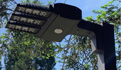
Smart cities are popping up all over the world, in the U.S., Europe, China and other regions. The LED lighting boom has driven up energy efficiency and reduced the carbon footprint of cities, while enabling increasing connectivity. Streetlight poles are serving as hosts for radios used in cellular and mesh networks for IoT and other applications (see Figure 1).
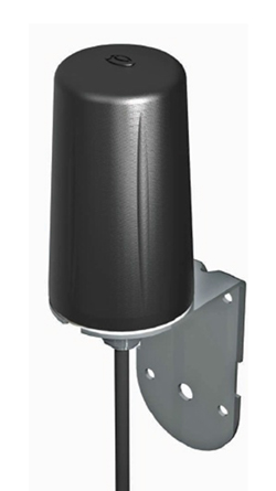
As was the case with millions of smart meter deployments during the last decade - which used inefficient, stamped-metal antennas inside the housings - LED street light installations are expected to have network connectivity issues, either a loss of network coverage or gaps in the desired coverage areas in 5 to 10 percent of the installations. To boost range and coverage, local authorities and wireless service providers can deploy external booster antennas outside the photocell housings (see Figure 2). Doing so requires careful attention to ensure the safety and integrity of the electrical isolation between the antenna and the pole, which is usually constructed from extruded metal. Often, the radio is powered directly from the 120/240 V AC power. Without isolation, the radio is vulnerable to lightning surges in the kV range, creating a shock hazard to utility workers and the general public.

Figure 1 Typical LED streetlight with topside photocell containing a radio.

Figure 2 External booster antenna. Courtesy: Panorama Antennas.

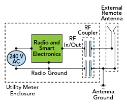
Figure 3 Block diagram of a typical application using the coupler.
To address this, RF Savvy has developed an ultra-wideband 50 Ω coupler isolation circuit, providing up to 10 kV isolation while covering all the major communications bands:
- Cellular at 600, 700, 850, 900, 1800, 1900 and 2100 MHz.
- ISM at 900 MHz and 2.4 GHz.
- GPS at 1575 MHz.
- Iridium LEO satellites at 1616 MHz.
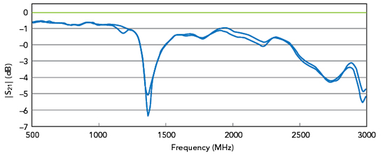
The RFC001B-A RF coupler is compact with a low profile, measuring 45 mm x 45 mm x 0.8 mm, enabling the coupler to be deployed inside the photocell unit on the top of the lightpole. Figure 3 shows a block diagram of the typical application, with the RF coupler electrically between the radio and external booster antenna. The capacitive coupling structure isolates both the signal and ground paths of the RF circuit, incurring less than 1 dB insertion loss in the sub-1 GHz frequency bands. Figure 4 shows the typical insertion loss. For NB-IoT applications at 600 MHz, the insertion loss is less than 1 dB. The coupler’s frequency response extends through the 2.4 GHz ISM band, with an insertion loss typically less than 2.5 dB at the upper end. The typical VSWR is better than 1.3:1 across the communications bands.

Figure 4 Typical insertion loss of the RF coupler.
Input and output connections to the coupler are via MMCX jack surface-mount connectors. The maximum RF input power is rated at 2 W, and the coupler has a specified operating temperature range from −40°C to +85°C. The exterior coating is UL 94V-0 rated.
Tens of thousands of these couplers have been implemented on LED streetlights in cities across the U.S. and Europe, enabling a wide range of smart city applications.
RF Savvy Technologies LLC
Santa Rosa, Calif.
www.RFSavvy.com
(707) 360-8915
