
Yttrium-Iron Garnet (YIG) Filters
Many companies offer YIG filters for civil and military applications in spectrum analyzers, sweep generators, ECM receivers, broadband test equipment and frequency synthesizers (see Table 5). These filters use single crystal synthetic YIG spheres as microwave resonators and are magnetically tunable over broad frequency ranges. YIG filters are used for their high Q factors, typically between 100 and 200, and their electronic tunability.

YIG filters use a permanent magnet and a small coil for frequency correction and thermal compensation. For the most models, the operating temperature is from -54°C to +85°C. The slope Scontrol of the modulation characteristic is 10 to 30 MHz/mA depending on the model, and its deviation from linear over the tuning range is typically not more than 0.5 percent. The saturating power level of the input signal Pin sat is only about 10 dBm.
Tuning hysteresis depends on the tuning step and is proportional to the operating frequency (it does not exceed 20 MHz at a frequency of 20 GHz). The minimal width of the passband BW3dB is determined by the resonator’s unloaded Q and spurious parameters associated with filter construction. It may be constructed as a separately packaged module with coaxial connectors (see Figure 6), or in a PCB surface mount package.

Fig. 6 YIG-tuned bandpass filter (Courtesy of Micro Lambda Wireless).
Some filters are distinguished by relatively small tuning ranges with narrow rejection bandwidths, high linearity and little hysteresis, while others have wide tuning ranges (2 to 18 GHz), but with relatively broader passbands, poorer linearity and greater hysteresis.
Thin and Thick Film Filters
Most BPFs are based either on discrete components or on an integrated ceramic structure. In the ceramic structure, layers of ceramic dielectric material and metal alloy electrodes are interleaved and then sintered at high temperature. This process introduces component variability in dielectric properties (loss, dielectric constant and insulation resistance) as well as variability in electrode conductivity and physical size.
Thin-film BPFs eliminate these uncertainties. For frequencies from 0.75 to 67 GHz, filters thin film technology may be used, the same thin film technology that is commonly used for producing semiconductor devices. Applying this to the manufacture of BPFs has enabled the development of components where both electrical and physical properties are tightly controlled. For example, line width variations are less than 1 μm and layer thickness can be controlled to 100 Angstrom (see Figure 7). These manufacturing features create a thin film capacitive-based filter that has a repeatable frequency response.

Fig. 7 Typical topology of a thin film frequency filter (Courtesy of Dielectric Laboratories, Inc.).
Thin film capacitive BPFs save system size, weight and complexity while improving system reliability, manufacturability and performance; and, they have excellent reproducibility. Thin film technology is used for producing MEMS and BAW filters as well.
Monolithic Crystal Filters

Fig. 8 Cross section of a monolithic crystal filter (a) and its equivalent circuit (b).
The monolithic crystal filter (MCF) relies upon the piezoelectric effect exhibited in quartz for its operation (see Figure 8a). When signals appear across one pair of electrodes, they set up mechanical vibrations on the crystal. These are affected by the mechanical resonances of the crystal element, and only those signals within the passband of the filter are allowed across the crystal to be picked up by the second pair of electrodes. The equivalent circuit of a double-electrode MCF (see Figure 8b) has the ability to create a narrowband filter since the Q-factor of the quartz crystal is very high (up to several thousand). Coupling between input and output resonance nodes is determined by the electrode arrangement on the crystal surface. Higher-order filters are generally made by connecting several monolithic crystal filters in series. This enables the performance of multisection crystal filters to be replicated in a monolithic format (see Figure 9).
SAW and BAW Filters
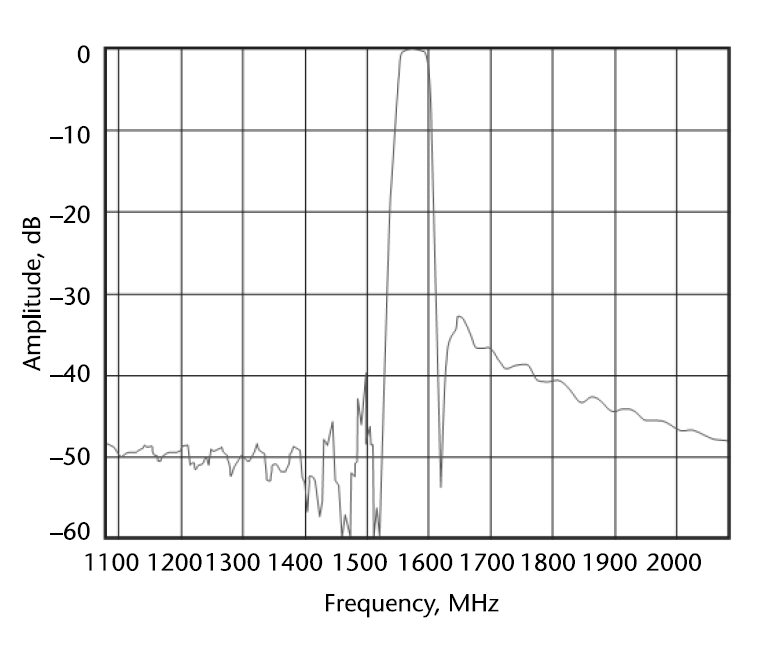

Fig. 9 Frequency characteristic of a monolithic crystal filter (a) and package (b) (Courtesy of Vectron International).
Electronic devices employing surface acoustic waves (SAW) use one or more interdigital transducers (see Figure 10) to convert SAWs to electrical signals and vice versa by exploiting the piezoelectric effect of certain materials (quartz, lithium niobate, lithium tantalate and lanthanum gallium silicate). These devices are fabricated by photolithography, the process used in the manufacture of silicon integrated circuits. Dimensions of the crystal and transducer arrangement specify the frequency bandpass response between input and output RF ports. To decrease the line length, one sometimes uses a reflective array. Dispersive SAW lines with linear characteristic delay versus frequency (compressed pulse width) have nonequidistant transducer electrodes. SAW filters operate in the RF range from 50 MHz to 2.5 GHz.

Fig. 10 Top view of in-line SAW delay line structure.
Bulk acoustic wave (BAW) filters can be used to implement ladder or lattice filters. BAW filters use reflections of the bulk acoustic wave in the piezo-electric crystal and typically operate at frequencies from 300 MHz to around 10 GHz.
A Thin-film bulk acoustic resonator (FBAR) is a device consisting of a piezoelectric material sandwiched between two electrodes and acoustically isolated from the surrounding medium. FBAR devices using piezoelectric films with thicknesses ranging from several micrometers down to a tenth of a micrometer resonate in the frequency range of roughly 100 MHz to 18 GHz. Technology for the production the crystal and SAW units allows for a simpler of implementation with better filtering ability.
Technical characteristics of selected SAW and BAW filters are summarized in Table 6.
