
The latest cable and sub-6 GHz 5G wireless networks present design and manufacturing challenges not only for the active semiconductors but also for widely used wire-wrapped ferrite RF components, such as transformers, splitters, couplers and baluns. As frequency and bandwidth requirements extend from hundreds of MHz to multiple GHz, the performance of these passive components must improve. Innovative designs, materials and manufacturing methods shrink their sizes while reaching higher operating frequencies and achieving broader bandwidths, by reducing parasitics that degrade performance and pose quality control challenges.
The increased demand of the information market has led to a massive growth in the amount of data that is acquired, transported and processed. Some forecasts suggest that data traffic in general will more than triple in the next five years, and mobile data traffic will grow by nearly 8x by 2023.1-2 Much of this traffic is expected to be carried by upcoming 5G networks.2 This explosion of data traffic is driving enhancements in the CATV networking infrastructure and mobile networks to accommodate higher data rates and, thus, higher frequency and bandwidth technologies for both active and passive components.
Hence, it is no surprise that there is a growing demand for higher performance and higher frequency wire-wrapped ferrite RF passives (wire-wound ferrites), specifically transformers, baluns, splitters and couplers.3-4 These components are used for impedance matching, balancing and signal power flow; they are crucial to the operation of virtually all digital and RF communication devices in the networking infrastructure. They are also found in many of the “last mile” broadband appliances. As with other digital and RF communication components, there are substantial considerations and design challenges to accommodate higher frequencies and higher bandwidths.
CHALLENGES AND DESIGN CONSIDERATIONS
In prior years, bandwidth requirements for wire-wound ferrite-based RF passives were limited to MHz frequencies. Recently, the trend has been to GHz bandwidths with an emerging demand for beyond 2 to 3 GHz. At higher frequencies, many factors can reduce wire-wound ferrite performance. For instance, the skin effect, which increases resistive loss proportional to frequency, begins to play a bigger role beyond a few hundred MHz. The proximity effect and fringe-field effects also contribute to greater losses at higher frequencies. Moreover, there is parasitic capacitance between the wires, known as inter-winding capacitance and parasitic series inductance. These factors tend to be less significant at low frequencies, where insufficient parallel inductance and core losses are the most significant contributors to insertion loss.
Hence, a significant challenge in the design and manufacturing of high bandwidth and high frequency wire-wound ferrite components is to achieve a balance between low and high frequency inductance for wideband operation. Other factors to consider are phase and amplitude balance across the bandwidth of operation. Generally, low frequency phase and amplitude balance are good, but challenges with respect to high frequency parasitics, manufacturing tolerances and wire quality become significant at higher frequencies.
Wire geometries and winding techniques also play a role in wire-wound ferrite impedance properties, as well as core size and dimensions. Hence, when designing components that are physically smaller, scaling factors associated with impedance must be carefully considered. Moreover, core material permeability is a function of temperature; with board-level densification and component proximity to high-power density devices, such as high-power GaN amplifiers, ensuring consistent impedance, balance and minimum loss during operation is a challenge.
In high performance semiconductors, many manufacturing considerations have been addressed through the use of highly automated manufacturing and quality control systems. This is yet to be viable with wire-wound ferrite components, as their unique physical construction has traditionally been beyond the capability of automated technologies. Greater manufacturing automation could dramatically improve tolerances, which directly impacts virtually all aspects of wire-wound ferrite performance.
New challenges are also arising, as emerging applications with unique needs demand custom designed components. Expertise with wire-wound ferrites has been, and continues to be, a niche area where few companies have the knowledge to design and manufacture innovative high frequency/high bandwidth wire-wound ferrites.
TECHNIQUES, METHODS AND APPROACHES
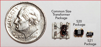 Figure 1 Common surface-mount transformer with soldered leads compared to S20 and S21 packages with welded leads.5
One method to reduce the losses associated with higher frequencies is to reduce the overall size. Reducing the core geometry, while allowing for a much more compact and cost-effective component, also decreases the series inductance that degrades high frequency performance. Figure 1 compares a common size surface-mount transformer with reduced geometry packages. A MiniRF S21 package, for example, covers a seventh the area and enables much higher frequency and bandwidth operation. Minimizing the ferrite size provides manufacturing benefits, as well, while limiting the impact of parasitics, losses and board-level interference. Smaller wire-wound ferrite packages better accommodate the reduced lead pitches of the ICs used in the latest 5G wireless and high throughput data interconnect standards, such as DOCSIS 3.1.
Another package-level solution to enhance performance at higher frequencies is to eliminate solder - instead weld bond leads directly to the contacts. Welding eliminates the need for solder material, provides a mechanically stronger bond, enhances reliability and improves electrical performance over wide temperature ranges. Wire bonds are commonly used in IC packaging and high performance and high power RF/microwave devices for the very same reasons, allowing for tighter tolerances to be maintained for dimensionally sensitive wire-wound ferrites. Lead length tolerances are also improved, which impacts phase and amplitude balance.
Ferrite core material selection is key to achieving the desired inductance versus frequency. The frequency and temperature dependant permeability of the core is a major contributing factor to inductance over much of the operating bandwidth. For high bandwidth and high frequency wire-wound ferrites, a core material with high permeability at low frequencies and consistently decreasing permeability toward high frequencies is desirable. Moreover, a core material with permeability less sensitive to temperature and with a high Curie temperature greater than 150°C is necessary.
Wire selection is another design and manufacturing consideration. Wire size, length, geometric stability, braiding (if applicable) and wire laminate all impact impedance, parasitics and losses. Matching wire and core geometries is important, especially at higher frequencies where even small geometric imperfections can significantly influence performance.
Although manufacturing automation for wire-wound ferrites is evolving, there has been some innovation in wire-wound ferrite test automation. Automated post production testing captures full S-parameters over a wideband small signal sweep of each component. Figure 2 shows the performance of a directional coupler. The data generated includes return loss, insertion loss, coupling and directivity, plus calculated amplitude and phase balance. From there, standardized tuning procedures are used to address each component individually to ensure quality.
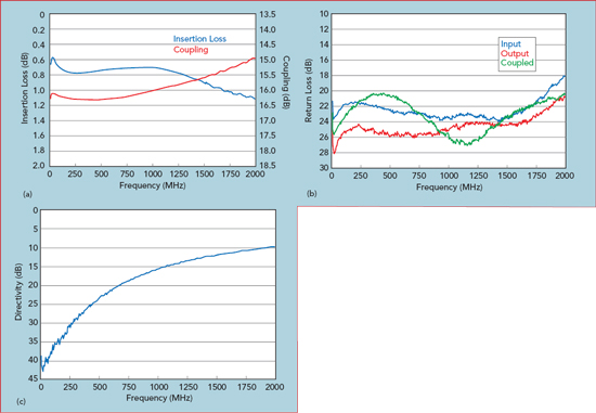
Figure 2 Measured insertion loss and coupling (a), return loss (b) and directivity (c) performance of a MiniRF 1.8 GHz wire-wound directional coupler.
CONCLUSION
In an industry where the trends in frequency and bandwidth are increasing, there is growing demand for high frequency and wideband wire-wrapped ferrite RF passive components meeting stringent performance criteria. Overcoming the design and manufacturing challenges requires smaller, higher performance components with tighter tolerances produced using more streamlined tuning and quality assurance methods.
References
- “Cisco Visual Networking Index: Forecast and Trends, 2017–2022 White Paper,” CISCO, February 2019, www.cisco.com/c/en/us/solutions/collateral/service-provider/visual-networking-index-vni/white-paper-c11-741490.html.
- “Mobile Data Traffic Growth Outlook,” Ericsson, June 2018, www.ericsson.com/en/mobility-report/reports/june-2018/mobile-data-traffic-growth-outlook.
- “Robust Electronics Production in Response to Digitalization Trends Drives the Global Inductors Market,” Global Industry Analysts Inc., August 2018, www.strategyr.com/MarketResearch/market-report-infographic-inductors-forecasts-global-industry-analysts-inc.asp.
- Data Bridge Market Research, “Explosive Growth on Global Inductor Market Globally by Key Companies as Taiyo Yuden Co. Ltd., Murata Manufacturing Co. Ltd., Panasonic Corp., Pulse Electronics, Vishay Intertechnonogy Inc.,” February 2019, reportsherald.com/explosive-growth-on-global-inductor-market-globally-by-key-companies-as-taiyo-yuden-co-ltd-murata-manufacturing-co-ltd-panasonic-corporation-pulse-electronics-vishay-intertechnonogy-inc/.
- MiniRF, www.minirf.com.