

TYPES OF AMPLIFIERS
Low-Noise Amplifiers
Low-noise amplifiers are used in input circuits of amplification stages for small signals mixed with noise in a limited frequency band. Amplifiers with NF less than 5 dB are usually considered low-noise amplifiers. For amplifiers in the millimeter-wave range (frequencies greater than 30 GHz) they may be considered low-noise with NF less than 15 dB. The achievable value of NF depends, to a large degree, upon an amplifier’s high cutoff frequency fhigh, output power Pout1dB, and environmental temperature. Characteristics of some models with low level of inherent noise are presented in Table I.

High Dynamic Range Amplifiers
Nonlinear phenomena with a growth in signal level are unavoidable in microwave amplifiers. If the signal is modulated in phase, frequency, or amplitude; then, as a result of intermodulation distortion of the third and fifth order, spectral components appear in the operating frequency band that cannot be eliminated in further stages with the help of frequency filtering. Dynamic range can be characterized as the amount by which the value of PoutIP3 exceeds the level of intrinsic noise; therefore to extend dynamic range, one can decrease the inherent noise level (i.e. NF) while simultaneously increasing PoutIP3. The linear figure of merit
LFOM = PoutIP3/Pout1dB (9)
is used by manufacturers to compare the linearity of various microwave amplifiers. Parameters of some high dynamic range amplifiers are shown in Table II.

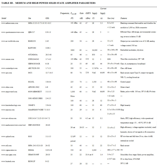
Solid-State Power Amplifiers
Identifying an amplifier as low, medium or high power is ambiguous: it is necessary to take into consideration the operating frequency and given manufacturing technology. Moreover, for high-power amplifiers the developer often faces limitations due to efficiency. For high power solid-state amplifiers, the most important parameters are Pout1dB, PoutIP3 and PAE. Parameters of some microwave solid-state amplifiers of medium and high power are listed in Table III. It should be noted that most manufacturers offer a wide range of products with different power levels for the same frequencies; the most typical examples are shown in the table.
Wideband Solid-State Amplifiers
Amplifiers of microwave signals with a wide (on the order of an octave) bandwidth and with the multi-octave bandwidths are used in ultrawideband (UWB) communication and in information transmission systems. Examples are presented in Table IV.

Tube Amplifiers - Klystrodes, Klystrons, TWTs, Amplitrons, Crossed-Field, and Gyro- Amplifiers
For RF power less than 1W in the frequency range 0.3 to 10 GHz, engineering solutions using surface mount or integrated solid state semiconductor technologies are typically used. They provide a gain of 15 to 20 dB in a single stage (up to 60 dB with cascading), PAE of 45 to 60 percent, passbands of 0.1 to 5 GHz, noise figures of 0.5 to 5 dB, and the dynamic ranges of not less than 30 to 40 dB. For medium power level devices there are engineering and economic tradeoffs between solid-state and microwave tube solutions.
In complex signal chains, one might find some stages implemented with solid-state components, while other parts employ vacuum tubes. Very high power and amplifiers and oscillators are implemented, as a rule, with vacuum tube microwave electronics.
The engineering requirements for amplifiers of medium and high power are a compromise of parameters such as linearity, gain, output power level, efficiency (PAE), bandwidth, weight and physical dimensions. One must also consider prime power needs, a means for air or water cooling and durability under expected environmental conditions such as temperature, pressure, moisture, shock, vibration and ionizing radiation. Some of these requirements can be better met with vacuum devices.
The modern multibeam construction of vacuum power amplifiers provides high and super-high output power. Tube active elements demonstrate markedly higher durability with respect to radiation. Although it is typical for traditional vacuum tubes to require power supplies with tens of kilovolts, it complicates (but does not exclude) their application in on-board and satellite equipment. Vacuum active elements of power microwave amplifiers are manifold.
A tetrode is an RF tube with a heated cathode, a control grid, a suppressor grid, and an anode. The tetrode is used as an amplifier of signal power for input signal frequencies from DC to frequencies where electron inertia becomes a limitation.
In the floating-drift klystron, electron inertia is used for bunching electron bundles during their transit between the input cavity gap and output cavities. Thus, the klystron is designed to amplify in the microwave range. For single-beam two-cavity or multicavity klystrons typical values of output power in continuous-wave mode achieve 50 kW at a gain 50 to 60 dB in a 10 percent relative frequency band. Multibeam klystrons utilize the oscillation excitation simultaneously in a set of from 8 to 36 beams, for which output power is summed.
A klystrode, or inductive output tube, represents a combination of a tetrode and a klystron: the input electron flow is modulated in density as in a tetrode and in velocity as in the klystron, while power is extracted much like a klystron. In such devices, PAE and linearity are essentially increased at high power, which explains its wide application in TV transmitters in the decimeter wavelength. In multibeam klystrodes the required supply voltages are reduced and realization of control grids becomes easier.
Traveling wave tubes (TWTs) can achieve 200 W using small diameter slow wave structures at frequencies from 10 to 25 GHz and with PAEs up to 60 percent for relative wide bandwidths of 1 to 2 octaves and the lifetimes up to 150,000 hours. TWTs with periodic slow wave, versus spiral, structures enable higher operating frequencies and PAEs, but with reduced the frequency bandwidth. In a multibeam TWT it is possible to reduce the supply voltages for a more compact construction.
An amplitron is an amplifying device that employs the principles of a magnetron with crossed electrical and magnetic fields and is more commonly called a crossed field amplifier (CFA). It provides a high PAE (up to 90 percent) and extremely high power due to frequency synchronization of the output oscillation to an external narrow-band input signal..
In gyrotron amplifiers the hollow screw-shaped electron flow and continuous interaction with the traveling wave tubes (as in TWT) are used. This provides electronic efficiency up to 70 percent in the millimeter wavelength range with the power up to 100 kW within tens of seconds. Experimental models of power amplifiers such as gyro-klystrons, gyro-twystrons, and gyro-TWTs are offered in the microwave and terahertz ranges.
A comparison of parameters of power vacuum amplifying devices in the UHF range is presented in Table V.

Pulse Amplifiers
Amplifiers intended for amplification of pulse microwave signals (pulse amplifiers) or for pulse modulation of low-power continuous-wave signals (pulse modulated amplifiers) differ in their requirements for high instantaneous bandwidth. Instantaneous bandwidth determines the duration of pulse rise and fall edges, and often employs saturation. For a normal amplifier, the approximate rise/fall time is equal 0.35/(3 dB-BW); however, if a sharp filter is used, rise and fall times can be roughly halved.
Phase linearity (group delay variation) must be quite good without resonances or sharp variations. To limit the overshoot of a square pulse Bessel filters are sometimes used.
The development of pulse RF amplifiers has progressed in several directions to meet different needs. First, highly efficient amplifiers operating in the Class D switching mode close to saturation (see Figure 3) have been improved. Second, wideband pulse video amplifiers have been developed for optical laser modulators in communication lines, which have bandwidths from DC to several tens of gigahertz. Third, for radar, measuring systems, and UWB applications, it is necessary to have radio frequency pulse amplifiers with a small (from 3 to 10) number of periods of carrier RF oscillation per pulse duration, high (up to hundreds of kilowatts) peak power and low duty factors.
Intermodulation Distortion and Linearization of Power Amplifiers

Figure 6. Predistortion digital linearizer.
The predistortion linearizer is implemented in the form of a serially connected controllable attenuator and phase shifter or a vector modulator. It is connected to the input of the power amplifier being linearized. It makes amplitude and a phase changes to the PA input signal based on a table of stored corrections to the nonlinear AM/AM and AM/PM characteristics of the amplifier (see Figure 6).
Feedforward linearization is accomplished by summating the main PA output of the amplified signal with a correcting signal from an auxiliary amplifier (AuxPA) (see Figure 7). The AuxPA input signal is created by comparing the input and output signals of the main PA in amplitude and a phase.

Figure 7. Feed forward linearizer.
The feedback linearizer samples the PA input and output, and feeds back a correction to the input in order to cancel nonlinearities (see Figure 8). Demodulation of the input and output signals is enabled by a reference local oscillator (LO) tuned to the carrier frequency. Quadrature I/Q components of the baseband signal are compared and with a vector modulator connected to the power amplifier input.

Figure 8. Cartesian feedback linearizer.
Related Publications
- H. L. Krauss, C. W. Bostian and F. H. Raab, Solid State Radio Engineering, New York, John Wiley & Sons, 1980.
- P. Wambacq and W. Sansen, Distortion Analysis of Analog Integrated Circuits, Kluwer Academic Publisher, Boston, MA, 1998.
- J. C. Whitaker, Power Vacuum Tubes Handbook, 2nd ed., Van Nostrand Re- inhold, New York, 1999.
- S. C. Cripps, Advanced Techniques in RF Power Amplifier Design, Artech House, Norwood, MA, 2002.
- J. Vuolevi and T. Rahkonen, Distortion in RF Amplifiers, Artech House, Norwood, MA, 2003.
- J. C. Pedro and N. B. Carvalho, Intermodulation Distortion in Microwave and Wireless Circuits, Artech House, Norwood, MA, 2003.
- S. A. Maas, Nonlinear Microwave and RF Circuits, 2nd ed., Artech House, Norwood, MA, 2003.
- B. Y. Banyamin, B. S. Virdee and A. S. Virdee, Broadband Microwave Amplifiers, Norwood, MA, Artech House, 2004.
- I. V. Lebedev (ed.), UHF Oscillators and Amplifiers, Radiotekhnika Publ., Moscow, 2005 (in Russian).
- A. Grebennikov, RF and Microwave Power Amplifier Design, McGraw-Hill, New York, 2005.
- I. V. Lebedev (ed.), Electronic UHF Devices, Radiotekhnika Publ., Moscow, 2008 (in Russian).
- P. Colantino, F. Giannini and E. Limiti, High Efficiency RF and Microwave Solid State Amplifiers, John Wiley & Sons, New York, 2009.
- A. S. Gilmour, Klystrons, Traveling Wave Tubes, Magnetrons, Crossed-Field Amplifiers, and Gyrotrons, Artech House, Norwood, MA, 2011.
- P. B. Kenington, “Methods for Linearization of RF Transmitters and Power Amplifiers,” Microwaves & RF, Vol. 38, January 1999, pp. 79–89.
- F. H. Raab, P. Asbeck, S. Cripps, P. B. Kenington, Z. B. Popovic, N. Pothecary, J. F. Sevic and N.O. Sokal, “Power Amplifiers and Transmitters for RF and Microwave,” IEEE Transactions on Microwave Theory and Techniques, Vol. 50, No. 3, March 2002, pp. 814–826.
- R. K. Parker, R.H. Abrams, B.G. Danly and B. Levush, “Vacuum Electronics,” IEEE Transactions on Microwave Theory and Techniques, Vol. 50, No. 3, August 2002, pp. 835-845.
- J. T. Stauth and S. R. Sanders, “Pulse-Density Modulation for RF Application: The Radio- Frequency Power Amplifier as a Power Converter,” IEEE Power Electronics Specialists Conference, June 2008.
- S. Sambandan, “High-Gain Amplifiers with Amorphous-Silicon Thin-Film Transistors,” IEEE Electron Device Letters, Vol. 29, No. 8, August 2008, pp. 882–884.
- F. M. Ghannouchi, “Power Amplifier and Transmitter Architectures for Software Defined Radio Systems,” IEEE Circuits and Systems Magazine, Fourth Quarter, 2010, pp. 56-63.
- F. Roger, “An Analog Approach to Power Amplifer Predistortion,” Microwave Journal, Vol. 54, No. 4, 2011, pp. 60-77.