Intermodulation Product Second-order Interferers in Dual-band Systems
Werner Wild
Spinner Company
München, Germany
The problem caused by the generation of intermodulation products within modern mobile communication systems where nonlinearities are present is already well known and discussed. A variety of attempts to reduce or eliminate intermodulation have been carried out and are reported in this article.
IM2: A NEW UNKNOWN CRITERION FOR DUAL-BAND SYSTEMS
The third-order intermodulation product was chosen in the past to evaluate the intermodulation performance of passive RF components. In PCN, GSM and PCS systems with certain carrier frequencies, it is possible that the third-order intermodulation product falls into the receive band and disturbs or even completely blocks discrete channels.
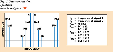
The formulas that describe the frequencies of the intermodulation products are well known. Figure 1 shows the intermodulation spectrum resulting from two signals and the formulas for determining the resulting frequency components.

With respect to a single-band system, this spectrum shows the third-order IM product as the one nearest to the generating frequencies and under some circumstances falling into the receive band. An example of a single-band GSM spectrum is shown in Figure 2 with transmit frequencies of f1 = 936 MHz and f2 = 958 MHz, and the IM3 product fIM3 = 914 MHz.

With respect to a dual-band system, this spectrum shows the second-order IM product suddenly as an additional interferer in the receive band. In the example shown in Figure 3 , the transmit frequencies are f1 = 936 MHz and f2 = 1850 MHz, and the IM2 product is fIM2 = 914 MHz.

THEORETICAL APPROACH
The questions of what power level the second-order IM product appears at and whether there is any relationship between the levels of other-order IM products is analyzed from a theoretical standpoint.
Based on two pure sinusoidal signals S1 cos(T1 t) and S2 cos(T2 t) with the amplitudes S1 = S2 = 1, by developing into potential rows up to the ninth order, the expressions for the second- and third-order IM products are determined to be

Again, developed up to the ninth order, the transmission characteristics of a component can be described by the polynomial

Pol(z) = A0 + A1 z + A2 z2 + A3 z3 + A4 z4
+ A5 z5 + A6 z6 + A7 z7 + A8 z8 + A9 z9 (3)
The factors z2 and z3 are the respective quadratic cubic elements of the transmission characteristic. The logarithm of the products of the rows for the transmission characteristic and the IM products provides the power levels of IM2 and IM3, depending on the included orders in the transmission characteristics.
This discussion already shows two things: The power levels of the second- and third-order IM products are absolutely independent from each other and only related to their respective transmission characteristics. Therefore, with a nearly quadratic characteristic (diode or transistor), the second-order IM product is dominant; with its cubic characteristic, the third-order IM product is also dominant.
The characteristic of a galvanic contact is unknown. Therefore, neither the power levels of the several IM products nor the relations between them can be calculated.
COMPARING IM2 AND IM3 MEASUREMENTS
Several comparable measurements of IM2 and IM3 were made to prove the conclusions of the theoretical approach and to provide additional information. The IM2 measurement was performed with f1 = 936 MHz and f2 = 1850 MHz at 2 * 20 W (+43 dBm). The IM product was measured at 914 MHz. The IM3 measurement was performed in the GSM band with f1 = 936 MHz and f2 = 958 MHz at 2 * 20 W (+43 dBm). The system sensitivity or self-intermodulation of the test bench was 180 dBc for IM2 and 178 dBc for IM3.
DEVICES UNDER TEST
Two pieces (each) of the following passive RF components were selected as devices under test (DUT):
* a jumper cable HCF 1/2" assembled with 2 * 7-16 male connectors; the connectors are soldered directly to the cable and consist of solid inner and outer conductors
* the same cable as above, but equipped with an adjustable diode in one of the connectors; the IM2 level was tuned to 150 dBc
* a 40 dB/100 W power attenuator
* a 3 dB/50 W power attenuator
MEASUREMENT RESULTS
Table 1 lists the test results. Figure 4 shows a graphical comparison of IM2 and IM3 performance. The jumper cables create neither IM2 nor IM3 in a measureable level. Therefore, the self-intermodulation of the test bench is displayed as a result.


The IM2 level of the jumper cable with diode was measured at 150 dBc. The IM3 level was approximately 9 dB lower. As estimated, the quadratic shape of the transmission characteristics of the diode is dominant.
In the case of the 40 dB/100 W attenuator, the measured IM2 level is 10 to 12 dB below the IM3 level. This result shows that the transmission characteristics of the attenuator are mainly cubic.
The measured IM2 level of the 3 dB/50W attenuator is 17 to 20 dB below the IM3 level. The cubic part of the transmission characteristics is dominant here as well.
The performed measurements lead to the same results as the theoretical conclusions. Knowing the levels of the discrete IM products the transmission characteristic of passive RF components can be calculated. To achieve reasonably accurate results at least the first five orders (even and odd) of IM products must be measured. Additional measurements for IM2 and IM3 with different materials and RF devices are necessary.
CONCLUSION
It has been shown that a complete evaluation of a passive RF device requires a specification for the second-order IM product effects when used in a dual-band system. The theoretical approach showed that no relationship or equation for calculating the power levels of the particular IM products can be given because the transmission characteristics of galvanic contacts are never known. This fact was proven by measurements in the RF lab. *
Werner Wild received his Dipl.-Ing. Degree in electrical engineering in 1987 from Fachhochschule Augsburg. He has been employed by Spinner GmbH since 1989 and has been the head of development and design since 1995.
