Computer simulations of |S11|, aperture efficiency, directivity and the radiation patterns in the E- and H-planes are shown in Figure 3. At 5.8 GHz, the gain is 12.95 dBi and the aperture efficiency is 86.75 percent. The impedance bandwidth is 340 MHz, i.e., |S11| < ‐10 dB from 5.73 to 6.07 GHz. Directivity is between 12.77 and 13.07 dBi, and aperture efficiency is between 83.34 and 86.75 percent.

Figure 3 Computer simulation of conformal antenna |S11| (a), directivity and aperture efficiency (b) vs. frequency and E-plane (c) and H-plane (d) patterns at 5.8 GHz.

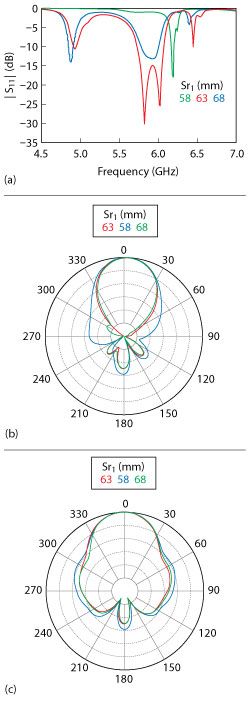
Figure 4 Influence of the cylindrical radius on |S11| (a), E-plane (b) and H-plane (c) antenna patterns.
Sensitivity Analysis
To evaluate the robustness of the design, the influence of factors affecting the stability of antenna performance was explored: the radius of the cylinder, the dielectric constant and the spacing of layers. Figure 4 shows the variation of |S11| and the antenna radiation patterns with the radius of cylinder Sr1 at 58, 63 and 68 mm. With decreasing radius, the center frequency increases, accompanied by a sharp decline in impedance bandwidth. With increasing radius, the impedance bandwidth is affected to a lesser degree. When the radius is 58 mm, its impact on the pattern, especially in the E-plane, is large; the side lobe and back lobe grow significantly. For a radius of 68 mm, the impact on the pattern is relatively small.

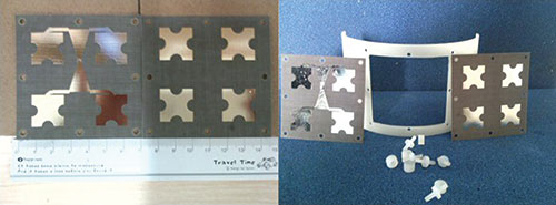
Figure 5 conformal antenna.

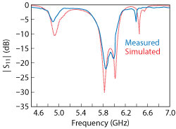
Figure 6 Measured vs. simulated |S11| .
The dielectric constant of the teflon dielectric plate changes with frequency and temperature. The influence of dielectric constant on antenna performance was evaluated for εr values of 2.05, 2.55 and 3.05. The corresponding antenna gains are 13.6, 13.7 and 13.4 dBi, indicating the dielectric constant has little influence on the pattern. For a double-layer antenna, the spacing between the parasitic layer and radiation layer has a strong influence on impedance bandwidth but little influence on operating frequency. Radiation patterns with different layer spacing show that with hz spacings of 2.05, 2.35 and 2.65 mm, antenna gains are 12.3, 12.95 and 12.46 dBi, respectively, indicating that variation in the spacing of layers over a narrow range has little influence on gain.
Experimental results
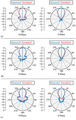
The prototype antenna is shown in Figure 5. Its reflection coefficient |S11| was measured with a vector network analyzer, and a comparison of the measured and simulated results is shown in Figure 6. They are in good agreement, demonstrating an impedance bandwidth of 320 MHz (|S11| < ‐10 dB from 5.73 to 6.05 GHz). Antenna patterns were measured at 5.7, 5.8 and 5.9 GHz (see Figure 7). They agree well with the simulation, especially at the center frequency of 5.8 GHz.

Figure 7 Measured vs. simulated antenna patterns at 5.7 (a), 5.8 (b) and 5.9 (c) GHz.
Conclusion
This article describes a novel, two-layer, stacked, microstrip, cylindrical conformal antenna using cross snowflake fractal patches. Based on the planar cross snowflake fractal patches, the structure of the conformal antenna was optimized by FEM to achieve high aperture efficiency and wideband properties at a center frequency of 5.8 GHz. The measured impedance bandwidth extended from 5.23 to 6.54 GHz (19.75 percent). The gain was
12.1 dBi, and the corresponding aperture efficiency was between
87.5 and 89.75 percent.
Acknowledgment
This work was supported by the National Natural Science Foundation of China (Grant Number: 61372043) National Basic Research Program of China (Grant Number: 2013CB328905) and the Sichuan Science Fund for Distinguished Young Scholars (Grant Number: 2015JQ0034).
References
- T. Nowicky, “Microwave Substrate Present and Future,” Workshop on Printed Circuit Antenna Technology, Vol. 13, No. 11, 1980, pp. 85–86.
- F. Chauvet, Conformal, Wideband, Dual Polarization Phased Antenna Array for UHF Radar Carried by Airship, PhD Thesis, UPMC/Sondra, Paris, 2007.
- V. Erturk and R. Roberto, “Efficient Computation of Surface Fields Excited on a Dielectric-Coated Circular Cylinder,” IEEE Transactions on Antenna and Propagation, Vol. 48, No. 10, October 2000, pp. 1507–1516.
- D. Herold, L. Griffiths and T. Fung, “Lightweight, High-Bandwidth Conformal Antenna System for Ballistic Helmets,” IEEE Military Communications Conference, October 2007, pp. 1–6.
- K. Wong, Design of Nonplanar Microstrip Antennas and Transmission Lines, John Wiley & Sons, 2004.
- M. Naser-Moghaddasi, R. Sadeghzadeh, M. Ghiamy, A. A. Neyestanak and B. S. Virdee, “An Elliptical Cylindrical FDTD Algorithm for Modeling Conformal Patch Antenna,” IEEE Transactions on Antennas and Propagation, Vol. 58, No. 12, December 2010, pp. 3990–3996.
- M. Heckler and A. Dreher, “Full-Wave and Fast Analysis of Conformal Microstrip Lines and Antennas,” URSI International Symposium on Electromagnetic Theory, October 2010.
- M. Heckler and A. Dreher, “Analysis of Conformal Microstrip Antennas with the Discrete Mode Matching Method,” IEEE Transactions on Antennas and Propagation, Vol. 59, No. 3, March 2011, pp. 784–792.
- C. Loecker, P. Knott, R. Sekora and S. Algermissen, “Antenna Design for a Conformal Antenna Array Demonstrator,” 6th European Conference on Antennas and Propagation, March 2012, pp. 151–153.
- M. Vouvakis, A Non-Conformal Domain Decomposition Method for Solving Large Electromagnetic Wave Problems, PhD Thesis, The Ohio State University, 2005.
- M. Bosiljevac, S. Skokic and Z. Sipus, “Analysis of Conformal Arrays Using Spectral Domain Approach - Comparison of Different Asymptotic Extraction Methods,” Proceedings of the 4th European Conference on Antennas and Propagation, April 2010.
- Z. Sipus, M. Bosiljevac and J. Bartolic, “Acceleration of Spectral Domain Analysis Method for Conformal Antennas,” International Workshop on Antenna Technology, March 2010.
- S. Khamas, “An Efficient Full-Wave Analysis of Irregular-Shaped Conformal Antennas in a Layered Spherical Media,” Proceedings of the 4th European Conference on Antennas and Propagation, April 2010.
- J. Wu, S. Khamas and G. Cook, “An Efficient Asymptotic Extraction Approach for the Green’s Functions of Conformal Antennas in Multilayered Cylindrical Media,” IEEE Transactions on Antennas and Propagation, Vol. 58, No. 11, November 2010, pp. 3737–3742.
- R. A. Martin and D. H. Werner, “A Reciprocity Approach for Calculating the Far-Field Radiation Patterns of a Center-Fed Helical Microstrip Antenna Mounted on a Dielectric-Coated Circular Cylinder,” IEEE Transactions on Antennas and Propagation, Vol. 49, No. 12, December 2001, pp. 1754–1762.
- B. Strojny and R. Rojas, “Characteristic Mode Analysis of Electrically Large Conformal Bifilar Helical Antenna,” Proceedings of the 4th European Conference on Antennas and Propagation, April 2010, pp. 1–5.
- J. Adams, S. Slimmer, T. F. Malkowski, E. B. Duoss, J. A. Lewis and J. T. Bernhard, “Comparison of Spherical Antennas Fabricated via Conformal Printing: Helix, Meanderline and Hybrid Designs,” IEEE Antenna and Wireless Propagation Letters, Vol. 10, December 2011, pp. 1425–1428.
- G. Palikaras, J. Vardaxoglou and George K. Palikaras, “Advances in Conformal Antennas Based on High Impedance and EBG Metamaterial Surfaces,” Proceedings of the URSI International Symposium on Electromagnetic Theory, May 2013, pp. 1094–1097.
- D. Gaetano, M. Ammann, P. McEvoy, M. John, L. Keating and F. Horgan “A Conformal UWB Directional Antenna,” 5th European Conference on Antennas and Propagation, April 2011, pp. 1113–1116.
- J. J. H. Wang, J. K. Tillery, K. E. Bohannan and G. T. Thompson, “Helmet-Mounted Smart Array Antenna,” Antennas and Propagation Society International Symposium, Vol. 1, July 1997, pp. 410–413.
- W. Jin, X. Yang, X. Ren and K. Huang, “A Novel Two-Layer Stacked Microstrip Antenna Array Using Cross Snowflake Fractal Patches,” Progress In Electromagnetics Research C, Vol. 45, 2013, pp. 95–108.
