
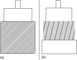
Figure 5 Served round-wire shield (a) and served flat-wire shield (b) construction.
Two additional shield types are shown in Figure 5: the served round-wire and served flat-wire shields. The served round-wire shield employs multiple, round-wire conductors wrapped in a spiral fashion around the dielectric. With the flat-wire version, thin, flat strips of metal, usually silver-plated copper, are spiral-wrapped about the dielectric and a layer of metalized polymer wrap is applied to bind the flat-wire bundle and reduce contact resistance. Served wire shields are used to enhance the cable’s “feel,” producing limp, flexible cables. Manufacturing is easy and quick, yielding low component cost. However, both types are prone to contact resistance changes with flexure, movement and temperature, reducing loss stability and shielding effectiveness.
The shielding effectiveness of a flexible coaxial cable improves as the outer conductor and shield configuration approach a continuous, one-piece construction, like the outer conductor of a semi-rigid cable. This assumes the material has a reasonably good level of conductivity at microwave frequencies. Designs that incorporate openings or gaps are susceptible to interference, i.e., receiving and radiating electromagnetic energy.
SHIELDING EFFECTIVENESS
Having discussed shielding types, we will examine the real world performance of microwave airframe cables. This particular cable type represents a unique subset of microwave cable technology, where the environment is the unpressurized portion of military combat and transport aircraft, and the cable assembly is generally used in radar and electronic warfare systems. These systems play a key role in threat detection, targeting, self-protection, communications and navigation; if the cables fail or malfunction, they risk equipment and, more importantly, lives. Because they reside in unpressurized environments, airframe cable assemblies must use a sealed construction. If conventional, unsealed cables are used, moisture-laden air will penetrate the cable’s dielectric with altitude-induced pressure changes, causing variation in electrical performance.
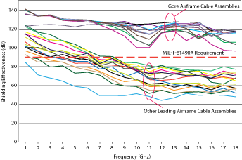
Figure 6 Shielding effectiveness of microwave airframe cable assembly families from two companies. The minimum specification per MIL-T-81490A (AS) is 90 dB.
Microwave airframe cables used in U.S. military aircraft must comply with the MIL-T-81490A (AS) standard, which stipulates a shielding effectiveness of no less than 90 dB over the cable assembly’s design frequency range. Figure 6 compares the shielding effectiveness of two companies’ microwave airframe cable assemblies, showing various models and assembly lengths and all rated to 18 GHz. Testing was conducted from 1 to 18 GHz per MIL-STD-1344, method 3008.
Why such a difference between the two sets of products? Connectors, connector termination and the cable are the three potential areas of RF leakage. To illustrate, Figure 7 shows the shielding performance of a 1 m microwave airframe cable assembly and the improvement when the connectors and connector termination area is covered with supplemental shielding material: adhesive-backed copper foil, 0.07 mm thick × 25 mm wide. Overlapping wraps of material were used to cover the area. With additional shielding, the trace still has the same general downward slope vs. frequency; however, the performance improves notably from 6 to 12 GHz.
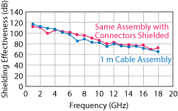
Figure 7 Applying supplemental shielding to the connectors improves the shielding effectiveness of a 1 m cable assembly.
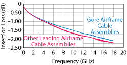
Figure 8 Insertion loss of served flat-wire cable assembly vs. Gore helically-wrapped, flat-wire assembly.
The poorer shielding effectiveness of the standard cable assembly from 6 to 12 GHz is significant enough to increase the insertion loss over the same frequency range (see Figure 8), as the “dip” in shielding effectiveness represents radiated power which never reaches the end of the cable assembly. The energy is radiated outside of the cable.