
A planar four-way wideband power divider with compact size, good isolation and output port impedance matching uses quarter-wavelength coupled lines, instead of the quarter-wavelength transmission lines used in a conventional Wilkinson power divider, to implement stopband rejection and the four-way power dividing function. Even and odd mode equivalent circuits are presented and design equations are derived. A compact planar four-way power divider is designed, optimized, fabricated and measured. Measured results show good agreement with simulation.
Power dividers play an important role in power-combining amplifiers and antenna arrays. Current development is focused on wide bandwidth,1-4 multi-band response,5-7 miniaturization,8,9 high isolation10,11 and harmonic suppression,12,13 as well as small size, low cost and ease of integration.14-19 Xu16 reported on a four-way power divider interconnecting power dividers with several output ports, but it was large. Xu et al.18 used composite right/left-handed transmission lines to construct parallel three-way and four-way power dividers;18 however, since no isolation elements were used, isolation and match at the output ports were poor. They mentioned that reasonable isolation, good output match and compact size are difficult to realize in multi-way planar power dividers.

Figure 1 Planar four-way power divider with stopband rejection.
Filters are needed in RF systems to reject unwanted signals. Power dividers and filters are often connected together to achieve low insertion loss, miniaturization and low cost. At present, power dividers with filtering are normally constructed in two types: Type I power dividers with harmonic suppression20,21 and Type II power dividers with bandpass filter responses.22-29 Power dividers with single and dual bandpass responses have been developed;30,31 however, planar multi-way power dividers with bandpass response or stopband rejection, good output isolation and good output impedance matching are very few.
In this article, we describe a compact, planar, four-way power divider with stopband rejection, good isolation and impedance matching at its output ports. The power divider is constructed using coupled lines. Its frequency response is similar to a coupled line filter. Coupled lines are utilized instead of the quarter-wavelength line in a conventional Wilkinson power divider to reduce the size. Measured results show that this planar four-way power divider with stopband rejection has several advantages: excellent input impedance matching, low insertion loss, a good balance of amplitude and phase at the output ports, good filter response and good isolation within the passband.
DESIGN
The coupled line four-way power divider (see Figure 1) can be described as equivalent to a combination of a coupled line filter and a Wilkinson power divider. Stopband rejection is realized with the same λ/4 microstrip lines of the Wilkinson power divider. The length (L1) of the coupled line is about λg/4, where λg is the guided wavelength of the microstrip line at the center frequency. Output ports 2 and 3 are located at the two ends of the upper folded microstrip line, while output ports 4 and 5 are located at the two ends of the lower folded microstrip line.
The operating bandwidth is determined by the coupling gap, S1, between the transmission lines, which can be obtained by simulation. Isolation resistors (R1 in Figure 1) are located between ports 2 and 3 and ports 4 and 5. Another isolation resistor, R2, is located between the two central coupled lines. Since the power divider is symmetric, the even/odd mode method can be used for analysis.

Figure 2 Odd mode equivalent circuit.
EQUIVALENT CIRCUIT ANALYSIS
Under odd mode excitation, the symmetrical plane PP’ shown in Figure 1 is an electrical wall (see Figure 2). Part 1 in Figure 2 is a coupled line, which can be viewed as a four-port network. One of the four ports is a short circuit and another connects to the resistance R2. According to microwave network theory, part 1 can also be viewed as a two-port network. The two ports are designated 1 and 2, respectively. The impedance matrix elements of the two-port network are obtained as follows:

Z11, Z12, Z13, Z14, Z21 and Z22 are the impedance matrix elements of the four-port network. The transmission matrix [A1] of part 1 is obtained by the relationship between the impedance matrix and the transmission matrix. In addition, the transmission matrix [A2] of part 2 is obtained as follows:

where θ is the electrical length of part 3. The transmission matrix [A3] of part 3 is obtained by combining Equations 1 and 2.

Meanwhile, the admittance matrix [Y3] of part 3 is also obtained by using the relationship between the transmission matrix and the admittance matrix. The admittance matrix [Y4] is as follows:

The admittance matrix [Yw1] or transmission matrix [Aw1] of the entire network can be obtained by

When port 1 and port 2 are simultaneously matched, the following condition must be satisfied:


Figure 3 Even mode equivalent circuit.
where Aw1, Bw1, Cw1 and Dw1 are the elements of the transmission matrix [Aw1].
Under even mode excitation, the symmetrical plane PP’ is a magnetic wall, as shown in Figure 3. The analysis method is similar to the odd mode. According to transmission line theory, the input impedance Zin1 is determined by

Based on microwave network theory, the impedance matrix [Z2] of part 5 is

The transmission matrix [Aw2] of the entire network is determined in a manner similar to that for the odd mode analysis. When ports 3 and 4 are simultaneously matched, the condition that must be satisfied is

where Aw2, Bw2, Cw2 and Dw2 are the elements of [Aw2]. The isolation resistances R1 and R2 can be calculated by combining Equations 1 to 9 after the other parameters are confirmed.

Figure 4 Fabricated planar four-way power divider.
SIMULATION AND MEASUREMENT
To verify and demonstrate the design method and circuit performance, a four-way planar power divider was built on an RF-35 substrate with relative permittivity of 3.5, thickness of 0.508 mm and loss tangent of 0.0018. The circuit model was constructed in HFSS. After simulation and optimization, the dimensions of the fabricated planar four-way power divider were chosen to be L1 = 43.2 mm, L2 = 45.65 mm, L3 = 2 mm, W1 = 0.1 mm, W2 = 0.1 mm, W3 = 0.1 mm, S1 = 0.1 mm, R1 = 100 Ω and R2 = 100 Ω. A photograph of the fabricated planar four-way power divider is shown in Figure 4. The circuit size is just 0.014 × 0.26 λg.
Measured versus simulated results are shown in Figures 5 and 6. The measured input return loss is greater than 15 dB, while the simulated input return loss is greater than 20 dB over the operating frequency range, as shown in Figure 5a. The center frequency is about 1.05 GHz, and the 10 dB input return loss bandwidth is about 28 percent. Insertion loss is about 0.4 dB within the passband, and the 1 dB insertion loss bandwidth is about 45 percent. A maximum amplitude imbalance of ±0.15 dB is observed over the operating passband. Lower stopband rejection is greater than 15 dB from 0 to 0.45 GHz, while upper stopband rejection is greater than 15 dB from 1.75 to above 2.75 GHz.
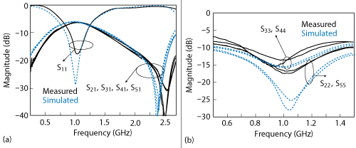
Figure 5 Simulated vs. measured insertion loss and |S11| (a) and |S22|, |S33|, | S44| and | S55| (b).
Measured return loss for the four output ports is greater than than 13.5 dB at the center frequency, as shown in Figure 5b. Since ports 2 and 3 are symmetric with ports 4 and 5, the curves of S22 and S33 are similar to the curves of S55 and S44, respectively. Because port 2 is not symmetric with port 3, the curve of S22 is not similar to the curve of S33. Likewise, the curve of S44 does not match the curve of S55.
The measured insertion phase of port 2 is similar with that of ports 3, 4 and 5 (see Figure 6a) with a maximum phase imbalance of ±2 degrees from 0.5 to 1.4 GHz. Amplitude and phase imbalance is likely due to fabrication and assembly tolerances. Figure 6b shows the isolation between output ports, which is greater than 15 dB over the passband.

Figure 6 Insertion phase (a) and simulated vs. measured |S32|, |S42|, |S43| and |S52| (b).
CONCLUSION
A compact planar four-way wideband power divider with stopband rejection uses coupled line technology not only provides a four-way power dividing function but also a bandpass response. Even and odd mode equivalent circuits are presented and design equations are derived. Measurement is in good agreement with simulation, verifying the theoretical analysis. This structure has excellent input and output impedance matching, low insertion loss, good balance of amplitude and phase at the four output ports, a filter response and good isolation within the passband.n
ACKNOWLEDGMENT
The work for this grant was supported by National Natural Science of China (Grant No: 61271026) and by the Program for New Century Excellent Talents in University (Grant No: NCET-11-0066).
References
- S. W. Wong and L. Zhu, “Ultra-Wideband Power Divider With Good In-Band Splitting and Isolation Performances,” IEEE Microwave and Wireless Components Letters, Vol. 18, No. 8, August 2008, pp. 518–520.
- M. E. Bialkowski and A. M. Abbosh, “Design of a Compact UWB Out-of-Phase Power Divider,” IEEE Microwave and Wireless Components Letters, Vol. 17, No. 4, April 2007, pp. 289–291.
- K. Song, Y. Mo, Q. Xue and Y. Fan, “Wideband Four-Way Out-of-Phase Slotline Power Dividers,” IEEE Transactions on Industrial Electronics, Vol. 61, No. 7, July 2014, pp. 3598–3606.
- K. Song and Y. Fan, “Broadband Travelling-Wave Power Divider Based on Substrate Integrated Rectangular Waveguide,” Electronics Letters, Vol. 45, No. 12, June 2009, pp. 4631–632.
- Y. Wu, Y. Liu, Y. Zhang, J. Gao and H. Zhou, “A Dual Band Unequal Wilkinson Power Divider Without Reactive Components,” IEEE Transactions on Microwave Theory and Techniques, Vol. 57, No. 1, January 2009, pp. 216–222.
- K. K. M. Cheng and C. Law, “A Novel Approach to the Design and Implementation of Dual-Band Power Divider,” IEEE Transactions on Microwave Theory and Techniques, Vol. 56, No. 2, February 2008, pp. 487–492.
- A. S. S. Mohra, “Compact Dual Band Wilkinson Power Divider,” IEEE Microwave Optical Tech. Lett., Vol. 50, No. 6, June 2008, pp. 1678–1682.
- P. K. Singh, S. Basu and Y. H. Wang, “Coupled Line Power Divider With Compact Size and Bandpass Response,” Electronics Letters, Vol. 45, No. 17, August 2009, pp. 892–893.
- X. Ren, K. Song, B. Hu and Q. Chen, “Compact Filtering Power Divider With Good Frequency Selectivity,” IEEE Microwave and Optical Technology Letters, Vol. 56, No. 9, September 2014, pp. 2122–2125.
- J. C. Kao, Z. M. Tsai, K. Y. Lin and H. Wang, “A Modified Wilkinson Power Divider With Isolation Bandwidth Improvement,” IEEE Transactions on Microwave Theory and Techniques, Vol. 60, No. 9, September 2012, pp. 2768–2780.
- L. Chiu and Q. Xue, “A Parallel-Strip Ring Power Divider With High Isolation and Arbitrary Power-Dividing Ratio,” IEEE Transactions on Microwave Theory and Techniques, Vol. 55, No. 11, November 2007, pp. 2419–2426.
- K. H. Yi and B. Kang, “Modified Wilkinson Power Divider for nth Harmonic Suppression,” IEEE Microwave and Wireless Components Letters, Vol. 13, No. 5, May 2003, pp. 178–180.
- D. J. Woo and T. K. Lee, “Suppression of Harmonics in Wilkinson Power Divider Using Dual-Band Rejection by Asymmetric DGS,” IEEE Transactions on Microwave Theory and Techniques, Vol. 53, No. 6, June 2005, pp. 2139–2144.
- Y. Wu, Y. Liu, Q. Xue, S. Li and C. Yu, “Analytical Design Method of Multiway Dual-Band Planar Power Dividers With Arbitrary Power Division,” IEEE Transactions on Microwave Theory and Techniques, Vol. 58, No. 12, December 2010, pp. 2832–2841.
- K. Song, Y. Fan and Y. Zhang, “Eight-Way Substrate Integrated Waveguide Power Divider With Low Insertion Loss,” IEEE Transactions on Microwave Theory and Techniques, Vol. 56, No. 6, June 2008, pp. 1473–1477.
- Y. Xu and R. G. Bosisio, “Design of Multiway Power Divider by Using Stepped-Impedance Transformers,” IEEE Transactions on Microwave Theory and Techniques, Vol. 60, No. 9, September 2012, pp. 2781–2790.
- K. Song and Q. Xue, “Ultra-Wideband Ring-Cavity Multiple-Way Parallel Power Divider,” IEEE Transactions on Microwave Theory and Techniques, Vol. 60, No. 10, October 2013, pp. 4737-4744.
- H. X. Xu, G. M. Wang, C. X. Zhang, Z. W. Yu and X. Chen, “Composite Right/Left-Handed Transmission Line Based on Complementary Single-Split Ring Resonator Pair and Compact Power Dividers Application Using Fractal Geometry,” IET Microwaves, Antennas & Propagation, Vol. 6, No. 9, June 2012, pp. 1017–1025.
- K. Song, F. Zhang, S.Y. Hu and Y. Fan, “Ku-Band 200-W Pulsed Power Amplifier Based on Waveguide Spatially Power-Combining Technique for Industrial Applications,” IEEE Transactions on Industrial Electronics, Vol. 61, No. 8, August 2014, pp. 4274–4280.
- M. G. Choi, H. M. Lee, Y. H. Cho, X. G. Wang and S. W. Yun, “Design of Wilkinson Power Divider With Embedded Low-Pass Filter and Cross-Stub for Improved Stop-Band Characteristics,” IEEE MTT-S International Microwave Symposium Digest, June 2011, pp. 1–4.
- K. K. M. Cheng and W. C. Ip, “A Novel Power Divider Design With Enhanced Spurious Suppression and Simple Structure,” IEEE Transactions on Microwave Theory and Techniques, Vol. 58, No. 12, December 2010, pp. 3903–3908.
- K. Song and Q. Xue, “Novel Ultra-Wideband (UWB) Multilayer Slotline Power Divider with Bandpass Response,” IEEE Microwave and Wireless Components Letters, Vol. 20, No. 1, January 2010, pp. 13–15.
- K. Song and Q. Xue, “Ultra-Wideband Out-of-Phase Power Divider Using Multilayer Microstrip-Slotline Coupling Structure,” IEEE Microwave and Optical Technology Letters, Vol. 52, No. 7, July 2010, pp. 1591–1594.
- T. H. Duong and I. S. Kim, “Single Section Wilkinson Type UWB Power Divider With Bandpass Filter and DC Block Characteristics in LTCC Technology,” IEEE MTT-S International Microwave Symposium Digest, May 2010, pp. 117–120.
- C. Zhuge, K. Song and Y. Fan, “UWB Power Divider Based on Signal Interference Techniques,” IEEE Microwave and Optical Technology Letters, Vol. 54, No. 4, April 2012, pp. 1028–1030.
- K. Song, S. Hu, Y. Mo, Y. Fan and C. Zhong, “Novel Bandpass-Response Power Divider With High Frequency Selectivity Using Centrally Stub-Loaded Resonators,” Microwave and Optical Technology Letters, Vol. 55, No. 7, July 2013, pp. 1560–1562.
- P. Cheong, K. I. Lai and K. W. Tam, “Compact Wilkinson Power Divider With Simultaneous Bandpass Response and Harmonic Suppression,” IEEE MTT-S International Microwave Symposium Digest, May 2010, pp.1588–1591.
- K. Song, Y. Mo, C. Zhuge and Y. Fan, “Ultra-Wideband (UWB) Power Divider With Filtering Response Using Shorted-End Coupled Lines and Open/Short-Circuit Slotlines,” AEU-International Journal of Electronics and Communications, Vol. 67, No. 6, June 2013, pp. 536–539.
- K. Song, X. Ren, F. Chen and Y. Fan, “Compact In-Phase Power Divider Integrated Filtering Response Using Spiral Resonator,” IET Microwaves, Antennas & Propagation, Vol. 8, No. 4, March 2014, pp. 228–234.
- Z. Zhang, Y. C. Jiao and Z. B. Weng, “Design of 2.4 GHz Power Divider With Harmonic Suppression,” Electronics Letters, Vol. 48, No. 12, June 2012, pp. 705–707.
- Y. C. Li, Q. Xue and X. Y. Zhang, “Single- and Dual-Band Power Dividers Integrated with Bandpass Filters,” IEEE Transactions on Microwave Theory and Techniques, Vol. 61, No. 1, January 2013, pp. 69–76.
Kaijun Song received his master’s degree in radio physics and his Ph.D. degree in electromagnetic field and microwave technology from the University of Electronic Science and Technology of China (UESTC), Chengdu in 2005 and 2007, respectively. Since 2007, he has been with the EHF Key Laboratory of Science, School of Electronic Engineering, UESTC, where he is currently a full professor. His current research fields include microwave and mmWave/THz power-combining technology; UWB circuits and technologies; microwave/mmWave devices, circuits and systems; and microwave remote sensing technologies.
Yu Zhu received his bachelor’s degree in electrical information engineering from Southeast University Chengxian College in 2014, and is currently pursuing his master’s in electrical engineering at UESTC. His research interests are in the areas RF/microwave and mmWave devices.
Shunyong Hu received his bachelor’s degree in applied physics from Shandong University of Science and Technology, Qingdao, Shandong in 2010 and is currently working toward his Ph.D. degree in electromagnetic fields and microwave technology at UESTC. His research interests include microwave and mmWave power-combining technology and microwave passive component design.
Fan Zhang received his bachelor’s degree from the Hefei University of Technology, Hefei in 2012. He is currently working toward his Ph.D. in the School of Electronic Engineering, UESTC. His research interests are microwave/mmWave passive structures, including filters and power dividers/combiners. He is also involved in the investigation of quasi-optical, beam-shaping techniques, diffractive optics and reflector design.
Maoyu Fan received her bachelor’s degree in physics from UESTC in 2014 and is currently working toward her master’s degree at UESTC as well. Her current research interests include electromagnetic, metamaterials and microwave/mmWave devices, circuits and systems.
Yong Fan received his bachelor’s degree from Nanjing University of Science and Technology, Nanjing, Jiangsu in 1985 and his master’s degree from UESTC in 1992. He is a senior member of the Chinese Institute of Electronics. His research interests include mmWave communication, electromagnetic theory, mmWave technology and mmWave systems.