Vector Signal Measurement for 38 GHz Digital Radio Applications
G. Samuel Dow, Jeff Yang and Kuo-Hsiung Yen,
TRW, Electronics Technology Division
Redondo Beach, CA
Robert Matreci, Eric Spotted-Elk, Stephen Pettis and Long Trinh
Hewlett-Packard Co., Santa Rosa Systems Division
Santa Rosa, CA
Broadband access using millimeter-wave digital radio technology has generated significant interest during the past several years. This technology is especially attractive for the implementation of a low cost, rapidly deployable last-mile interconnection solution between fiber-optic networks and service hubs. From a signal distribution point of view, two basic classes of radio systems exist: point-to-point and point-to-multipoint.
A point-to-point radio system is a dedicated link to provide short-haul voice and data communication between two business network centers. The licensed frequency spectrum allotted for short-haul radio links is 15, 18, 23, 26, 38 or 50 GHz. Data capacities range from a single DS-1 (1.544 Mbps) to DS-3 (44.736 Mbps).
A point-to-multipoint radio system provides voice and data communication services between multiple subscribers with a shared hub. The Federal Communications Commission has licensed the 27.5 to 28.35, 29.1 to 29.25 and 31 to 31.5 GHz bands for local multipoint distribution system (LMDS) service. Because of the availability of the wide bandwidth (850 MHz), very large downstream data capacity can be achieved.
With few exceptions, most millimeter-wave radio systems currently under development are based on digital communication implementation. Depending on the applications, various modulation schemes are being implemented from quadrature phase-shift keying (QPSK) to 64 quadrature amplitude modulation (QAM). Data rates range from T1 (1.544 Mbps) to DS-3 (44.736 Mbps), and a higher rate to 155 Mbps (OC-3).
Modern RF wireless communication systems use advanced vector signal measurement techniques to accurately measure the dynamic behavior of the RF subsystems and the integrated digital/RF systems. In the past, these types of tests were not performed at bandwidths above 7 MHz and millimeter-wave frequencies due to a lack of suitable test capabilities. This limitation has greatly curtailed the ability for transceiver manufacturers to speedily develop low cost, high performance transceiver products for digital radio applications. However, recent advances in wide-bandwidth vector signal analyzer (VSA) test equipment from leading test equipment suppliers are gradually lifting these barriers.1 In this article, a 38 GHz vector signal measurement test set is demonstrated and the application of this test set for performing a vector signal analysis of a 37 to 40 GHz power amplifier (PA) module is presented.
Why Vector Signal Measurement?
Digital radios offer a distinct performance advantage over their analog counterparts as well as system flexibility. However, the employment of digitally modulated RF carriers has created new challenges to RF testing. Traditional RF test methods with CW tones are no longer adequate to describe the performance and behavior of RF components and subsystems under digitally modulated test stimuli, and new test methods using vector signal modulation and demodulation are now required. For example, for an RF transmitter, instead of measuring the output 1 dB compression power and the third-order intercept point under CW test conditions, the vector signal test method measures in-band power, out-of-band power (that is, adjacent-channel power ratio) and error vector magnitude (EVM) under digitally modulated test stimuli.
There are significant benefits to adopting this new digital/RF test methodology: Digital test data - same or similar to those used in the field - now can be used to characterize the dynamic behavior of components, RF subsystems and integrated digital/RF systems. Second, digital correction solutions can be easily employed to correct any impairment caused by imperfection in RF subsystems. Finally, digital/RF tests provide direct and effective diagnosis of impairments and malfunctions, such as misalignments in the modulator and demodulator, PA nonlinearity, phase noise in the frequency source and clock recovery circuit, channel crosstalk and interference.2,3
Modulator and PA Design Considerations
A digital communication system that uses a high level modulation scheme, such as 16- and 64QAM, requires a high degree of modulation accuracy in the output transmitter signal to achieve the system's low bit error rate (BER) performance. A millimeter-wave transmitter can be implemented with either a direct frequency conversion approach or a dual-frequency conversion approach, as shown in Figures 1 and 2 , respectively. 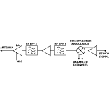 Direct frequency conversion has a simpler architecture; however, it requires a very linear millimeter-wave direct IQ modulator, which is a design challenge. On the other hand, the dual-frequency conversion approach can achieve very good modulation accuracy at the expense of higher hardware complexity.
The components that have the greatest impact on the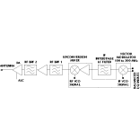 transmitter's modulation accuracy are the modulator and output PA. For multilevel signaling, a linear quadrature modulator is required. Important properties of a linear quadrature modulator include good dynamic range with linear transfer characteristics, low I/Q gain imbalance and quadrature error, and low DC offset. It is often necessary to align the modulator by adjusting these input I and Q parameters, including possible correction for I/Q imbalance vs. baseband frequency.
Nonlinearity of a PA also degrades the transmitter's modulation accuracy by introducing AM/AM and AM/PM distortions. Traditionally, linearity of the PA is achieved by a backed-off mode of amplifier operation. Output power back off can range from 4 to 10 dB depending on the linearity requirements. Thus, for a 1 W linear transmitter, the PA requires 2.5 to 10 W output power capability. This capability significantly increases the radio equipment cost. In fact, developing a high output PA at an acceptable cost remains a major challenge to RF component suppliers.
Other impairments that could degrade the transmitter's modulation accuracy include interfering signals, close in spurs, LO feedthru and phase noise of frequency sources. The industry-wide standard to determine the modulation accuracy is EVM,4 which measures the phasor difference between an ideal reference signal and the measured modulated signal. This parameter is an aggregated measure of the signal imperfections due to I/Q imbalance, PA nonlinearity, oscillator phase noise and filter imperfection in a single specification. The EVM specification allows circuit designers the flexibility to trade off different design approaches and permits system designers to know explicitly the hardware's capability.
A Millimeter-wave Vector Signal Measurement System
A millimeter-wave vector signal measurement system was configured to operate at higher Ka-band frequencies. It consists of a millimeter-wave modulator and a demodulator test bed. A functional block diagram of the complete vector signal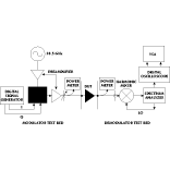 measurement system is shown in Figure 3 . The demodulator test bed is essentially an HP 71000T wideband VSA system, which extends the measurement bandwidth of the HP 89410 VSA from 7 MHz to over 200 MHz.1 The system has a maximum coax-input frequency of 26.5 GHz and can be extended to 110 GHz with external harmonic mixers. The LO for the harmonic mixer is provided by the output of the HP 70910A spectrum analyzer's internal LO source module.
The modulator test bed includes an HP E4433B digital modulation signal source to generate a digital I/Q data stream and an HP 83650B frequency synthesizer to generate the LO for the modulator. The digital data stream was generated, intersymbol interference (ISI) filtered and passed through a digital-to-analog converter (DAC) to form a band-limited analog waveform for driving the millimeter-wave quadrature modulator.
The modulator used in this case is TRW's model YQH122C monolithic quadrature modulator. Figure 4 shows a layout of the YQH122C MMIC. This monolithic high electron mobility transistor (HEMT) MMIC consists of two binary phase-shift keying (BPSK) modulators, a phase shifter and a power splitter connected to perform a vector modulator function. Each BPSK modulator is based on a double-balanced ring mixer structure,5 which features good amplitude and phase balance. The quadrature modulator circuit performance was evaluated with a single-sideband frequency upconversion test. At 38.5 GHz, the measured conversion loss for the desired sideband is 9 dB with 20 MHz IF. The measured image rejection and carrier suppression are > 25 and > 30 dB, respectively. The overall system's data rate is limited by the digital signal generator to 12.5 Msps. Higher bandwidth signals are achieved using a VXI-based signal generator (based on a special option of the HP E6432A microwave synthesizer).
The first test is to measure the signal quality of the overall measurement system with the YQH122C modulator in place by connecting the output of the modulator test set to the input of the demodulator test set. Four different modulation formats were chosen: QPSK, offset QPSK (OQPSK), p/4 differential QPSK and 16QAM. The frequency synthesizer was set to 38.5 GHz. The I/Q digital data rate was set to 12.5 Msps along with a square-root raised cosine lowpass filter with a (excess bandwidth ratio) set to 0.5.
Figures 5 , 6 , 7 and 8 show four VSA output displays under four different 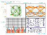
 modulation conditions. Each VSA display contains a vector or constellation diagram, eye diagram, error vector time display, error summary and symbol table. In all four cases, the symbols in the constellation diagrams have shown a small amount of spread. All eye diagrams show good eye openings. The average EVM ranges from three to 5.5 percent for these four cases. These levels of modulated signal accuracy should be adequate for
 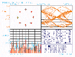 most system applications. The measured
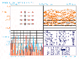 EVMs also include contribution from the demodulator test set since no independent calibration is performed on the demodulator test bed.
A 38 GHz 1 W PA Module
A vector signal measurement system was used to characterize TRW's HPA117 PA module, which operates from 37 to 40 GHz with a P1dB > 30.5 dBm across the full band. Figure 9 shows a photograph of the PA module. Internal to the PA module are three APH309C MMICs. One PA module is used as a driver, and the output stage consists of two PA modules combined through Wilkenson couplers. The APH309C MMIC is a two-stage balanced amplifier design based on TRW's 0.15 mm InGaAs pseudomorphic HEMT (pHEMT) device technology. It delivers > 12 dB linear gain and has an output P1dB > 29 dBm. The PA module has built-in DC and control functions and requires only +6 V and -5 V supplies. The input and output RF ports are standard WR-28 waveguide interfaces located on the bottom side of the housing. The module is designed for 37 to 40 GHz point-to-multipoint base station applications.
 The small-signal performance of the HPA117 module is shown in Figure 10 . The unit has 21 to 23 dB linear gain across the 37 to 40 GHz band. The measured CW output power
 performance is shown in Figure 11 . P1dB at 37, 38.5 and 40 GHz is 30.7, 31.4 and 30.5 dBm, respectively. Power-added efficiency is approximately 11 percent. The measured two-tone output third-order intercept point (OIP3) and third-order intermodulation rejection (3IMR) performances are shown in Figure 12 . The measured OIP3 is approximately 40 dBm. A single carrier output power level (SCPL) of 26 dBm was
 achieved with a 3IMR level of 28 dBc.
Vector Signal Measurements of the PA Module
An HPA117 PA module was then inserted into the vector signal measurement system. The first test used a QPSK digital modulation waveform. The RF carrier was set to 38.5 GHz and the I/Q digital data rate was set to 12.5 Msps with a = 0.5. Figure 13 shows the two VSA output displays corresponding to two input power levels of 0 and +14 dBm. A vector diagram displays the instantaneous output power behavior of the PA module. From these two vector diagrams, power compression is clearly evident at a Pin = +14 dBm drive level with the vector traces compressed around the corners along with symbol spreading occurring at the constellation points. The EVM also increased from 5.2 percent rms to 8.5 percent rms. This amplitude compression causes the frequency spectrum to spread into adjacent channels, which could create an adjacent-channel interference problem.


The PA module was further tested with a 16QAM digital modulation input. As before, the data rate was set to 12.5 Msps with a = 0.5. Figure 14 shows the VSA displays at four different input power levels (0, +8, +10 and +12 dBm) and their corresponding CW output power levels. As the input power level increases, the symbol constellation becomes increasingly rounded with the symbol clusters increasingly spread out at their symbol locations. In addition, the eye diagrams start to show richer accumulation of noise at the decision line due to ISI. The closure of the eye opening makes signal detection at the receiver more difficult, thus resulting in higher system BER. The measured average EVM increased from 4.4 percent rms at Pin = 0 dBm to 15.65 percent rms at Pin = +12 dBm. It is worthwhile to note that the PA module maintains fairly good modulation quality at an output power of approximately 1 W. It is also interesting to compare the EVM results from QPSK and 16QAM modulation. As expected, the QPSK modulation clearly has a better modulation quality performance, leading to a higher output power capability.
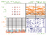
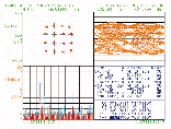
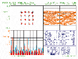

Table 1 lists the PA module linearity performance measured using three different methods: a single-tone CW, two-tone intermodulation and a 16QAM vector signal. As the input power increases from 0 to +12 dBm, the single-tone CW measurement shows a 1.8 dB gain reduction, the two-tone OIP3 decreases by 2.9 dB and the 16QAM EVM increases from 4.4 percent rms to 15.6 percent rms. All three methods characterize PA linearity performance; however, only the vector signal method provides insight into the PA nonlinear behavior under digital modulation. It should also be noted that since the modulator test bed has not gone through an alignment or calibration prior to device test, the measurement was actually for a complete direct modulation transmitter, which consists of a quadrature modulator, frequency source and PA module.
|
Table I | |||||
|
Input Power (dBm) |
Single-tone CW Output Power (dBm) |
Single-tone CW Gain Compression (dB) |
Two-toen (OIP3) (dBm) |
Two-tone SCPL/3IMR (dBm/dBc) |
16QAM EVM (% rms) |
|
0 |
22.2 |
0 |
40.5 |
19/43 |
4.4 |
|
8 |
29.8 |
0.4 |
39.4 |
26.4/26 |
7.3 |
|
10 |
31.4 |
0.8 |
38.3 |
27.8/21 |
11.4 |
|
12 |
32.4 |
1.8 |
37.4 |
28.4/18 |
15.6 |
Conclusion
A 38 GHz vector signal measurement system has been demonstrated. Key to the system are a TRW Ka-band monolithic quadrature modulator and an HP 71000T wideband signal analyzer. The system is flexible in providing various digital modulation formats. The modulation quality of the test system is measured by EVM and is less than six percent rms. The system was used to characterize a 37 to 40 GHz 1 W PA module with QPSK and 16QAM digital modulation. The PA module linearity performance was measured and compared using three different methods: single-tone CW, two-tone intermodulation and vector signal measurement. The vector signal measurement test method allows sophisticated digital/RF parametric tests to measure the dynamic behavior of the RF system under digital test stimuli. The new test method provides the possibility for more meaningful product specification, trade-offs between digital and RF functions, and the development of a streamlined test methodology for future millimeter-wave digital radio RF product development.?
References
1. "HP 71000T E72 Wideband Vector Signal Analyzer Installation and Operating Guide," Hewlett-Packard, February 1999. Also see "HP E3830 Series Wide Bandwidth Vector Signal Analysis Systems," (http://www.tmo.hp.com/tmo/datasheets/English/HPE3830.html).
2. "Using Vector Modulation Analysis in the Integration, Troubleshooting and Design of Digital RF Communications Systems," Hewlett-Packard Product Note 89400-8 (http://www.tmo.hp.com/tmo/Notes/English/5091-8687E.html).
3."10 Steps to a Perfect Digital Demodulation Measurement," Hewlett-Packard Product Note 89400-14A (http://www.tmo.hp.com/tmo/Notes/English/5966-0444E.html).
4."Using Error Vector Magnitude Measurements to Analyze and Troubleshoot Vector Modulated Signals," Hewlett-Packard Product Note 89400-14.
5."A Monolithic Broadband Double Balanced EHF HBT Star Mixer with Novel Microstrip Baluns," 1995 IEEE MTT-S Digest, pp. 119-122.
