Low Cost Briefcase Satphone Terminal Antennas
Two low cost L-band briefcase satphone terminal antennas, a two-element linear array of probe-fed metallic discs and a 2 x 2-element sequential feed planar array of aperture-coupled microstrip patches are investigated. The two antennas were tested indoors in an anechoic chamber and outdoors while connected to an NEC S1 transceiving terminal. A comparative study shows that the 2 x 2-element array is a superior choice having 14 dBi gain, less than 1.6 dB axial ratio over the global mobile satellite communications frequency band of 1.525 to 1.661 GHz and high quality voice communications via Optus B series satellites.
Nemai C. Karmakar and Marek E. Bialkowski*
Nanyang Technological University, School of Electrical and Electronic Engineering Singapore
*University of Queensland, Computer Science and Electrical Engineering Department
St. Lucia, Australia
Mobile satellite communications is an emerging technology that shapes the planet like a global village. In contrast to cellular-based mobile communications, which due to economical reasons is restricted mostly to densely populated areas, land mobile satellite communications represents an ideal way of putting people in remote places in touch with the rest of the world. This communications capability is irrespective of geographic features such as mountains, lakes, rivers and oceans. With the recent introduction of new domestic mobile satellite communications services using geostationary satellites1 in countries such as Australia (Mobilesat), Japan (N-star) and the US (AMSC), there has been a demand for antenna systems that would allow these voice, data and facsimile services to be accessed. Generally, two types of antenna systems can be used to access mobile satellite services: stationary portable systems, usually of briefcase type, and fully mobile systems such as those installed on a land vehicle.
Portable/briefcase terminals are very popular for international businessmen, construction workers, miners, emergency crews, relief workers and journalists.2 Some advantages of the portable system over its vehicle-mounted counterpart include its lighter weight, thus it can be carried as an attaché and used on a fixed platform; its ability to be used in locations where vehicle access is denied, such as in a hotel room, dense forests, relief areas and emergency situations; and its lower cost and higher reliability as it does not require satellite tracking electronics. Factors that require improvement over existing systems include size, weight and cost without sacrificing performance. Though briefcase antennas are plentiful in the market,3 their cost is a prohibitive factor for ordinary users. For example, a typical flat antenna for these applications costs more than US$1500.
The main goal of this article is to investigate two low cost, low profile antennas developed for briefcase satphone terminal use. To fulfill this goal, the antennas are designed and developed with very low cost materials and tested both indoors and outdoors. The developed antennas are a two-element linear array of cavity-backed metallic disc antennas and a thin-film, 2 x 2-element sequentially fed aperture-coupled patch antenna array. The configuration and specifications of briefcase terminal antennas are described and practical designs of both antennas are presented. Indoor testing results including radiation patterns, gain and axial ratio in an anechoic chamber, and outdoor field trials with an NEC S1 transceiving terminal are presented. Finally, a comparative study is performed based on the resulting performance, ease of manufacture and cost.
The Briefcase Satphone Terminal System Composition
A briefcase satphone terminal should include several components: a medium to high gain (on the order of 10 dBi) antenna; a transceiving terminal (also called a baseband processor) for modulation and demodulation of transmitted and received signals, respectively; a lightweight 12 V rechargeable battery as a power source; interface cables and sockets; auxiliary components such as a compass and map to aid in aligning the antenna with the satellite; and a casing preferably made from a lightweight microwave transparent material. Figure 1 shows a typical briefcase mobile satphone terminal. The briefcase houses a satphone handset, transceiving terminal and battery. A 2 x 2-element planar antenna is fitted under the lid of the briefcase. (The arrows show the signal flow directions.) The input of the antenna is connected to the terminal; a satphone handset is also connected to the terminal for voice communications. The battery energizes the system. The antenna is manually adjusted to lock to the satellite by changing the lid angle while the antenna is attached to the briefcase. Alternatively, the antenna can be taken out and placed in an elevated position to clear obstacles. The alignment process requires a few seconds and is aided with a compass and map.
Briefcase Satphone Terminal Operation
In the initial stage of operation, the correct look angle of the antenna is determined using the map and compass supplied with the system. The system is turned on and the received power levels are observed on the handset display. The antenna is then adjusted to acquire the maximum received power level. (This maneuver should take a few seconds.) Once the antenna is locked to the satellite with the strongest signal, voice communications can commence. The terminal also can be connected to a computer or fax machine for data and fax communications, respectively.
Satphone Antenna Specifications
Complete specifications4 for the briefcase satphone antenna, listed in Table 1 , depict electrical design parameters and the mode of operation. These specifications are valid for Inmarsat Mini-M, American AMSC and Australian Mobilesat and show that the antenna requires a bandwidth of nine percent (at the center frequency of 1.6 GHz) to cover both transmit and receive bands.
|
Table I | |
|
Electrical | |
|
Receive Frequency (MHz) |
1525 to 1559 (for Inmarsat, AMSC and Mobilesat) |
|
Transmit Frequency (MHz) |
1626.5 to 1660.5 (for Inmarsat, AMSC and Mobilesat) |
|
Polarization |
RHCP |
|
Beam |
fixed beam with minimum 30° 3 dB beamwidth |
|
Axial ratio (dB) |
6 maximum within the coverage region |
|
Gain (dB) |
10 or more |
|
Return loss (dB) |
10 |
|
Power Handling (W) |
> 3 |
|
Mechanical | |
|
Connector |
SMA/N/TNC |
|
Alignment |
manual to any angle |
|
Size/Shape |
minimum low profile with reasonable aerodynamic profile |
|
Operation |
portable and separable electronics |
|
Weight (kg) |
< 1.0 preferred |
|
Environmental |
waterproof, shock absorbent, and exposure to direct sunlight |
|
Operating temperature (ºC) |
-20 to 50 |
|
Commercial | |
|
Cost |
< $200 (a guide only) |
Satphone Terminal Antenna Design
Two low cost antenna systems have been designed. To keep the manufacturing cost as low as possible, the antennas are manufactured using low cost materials such as aluminum, thin laminates and plastic foams. The use of standard substrates, which are usually very expensive, is minimized. The detailed designs of the antennas are presented in the following sections.
The Two-element Linear Array
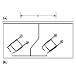
 Figure 2 shows the two-element linear array with two cavity-backed electromagnetically coupled circular metallic disc elements.5 The circular antenna element, cavity and supporting rectangular plate are made of aluminum. The feed network is etched on RO3003, a high frequency substrate material. The inter-element distance between the two
 elements is s. The coupling between antenna elements and the feed network is via coaxial probes, which in turn are electromagnetically coupled to the metallic disc via coaxial capacitors. This method enhances the bandwidth of the antenna elements to nine percent at 1.6 GHz.5 The right-hand circular polarization is achieved with orthogonal feed probes and two 3 dB hybrid couplers. The input power is divided equally between the antenna elements using a two-way T-junction power divider. The overall dimensions of the antenna are 26 x 13 x 1.4 cm and the weight is 2.5 kg.
The 2 x 2-element Sequentially Fed Array
Figure 3 shows the practical design layouts of the second design,  a multilayer 2 x 2-element sequentially fed array,6 as generated by HP EEsof Academy Layout. The four views show perturbation segmented patches rotated with a sequence of 90° clockwise, four apertures on the ground plane rotated using the same sequence, the corporate feed network layout of three Wilkinson power dividers and the plan view of the multilayer antenna composed of the three previously described layouts, respectively. As can be seen in the feed network layout, the outputs of the power divider are adjusted with delay lines providing the required 0°, 90°, 180° and 270° transmission phases of sequentially fed antenna elements.
The patches are etched on a thin-film laminate (0.76 mm thick) while the slots  and feed network are etched on the top and bottom sides of RO3003 material, respectively. The PCBs are placed on a PVC baseplate and secured as tiered layers with spacers, foams and screws. The manufactured antenna connected to a cable assembly and ready for testing is shown in Figure 4 . The overall dimension of the antenna is 26 x 26 x 1.4 cm and the weight is < 0.8 kg.
Indoor Testing Results
All of the testing was performed at the University of Queensland's anechoic chamber, which is equipped with an HP8030A microwave receiver. Note that the radiation patterns are shown only at 1.6 GHz as similar patterns are observed at the other frequencies within the Mobilesat frequency bands.
The Two-element Linear Array
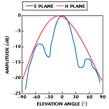
Figure 5 shows the plots of the two-element linear antenna array's measured radiation patterns in both E-plane (f = 0°) and H-plane (f = 90°) at 1.6 GHz. The antenna elements are placed at an inter-element distance s = 0.75 l. The measured 3 dB beamwidth in the E- and H-planes is 32° and 74°, respectively.
Two side lobes in the E-plane radiation pattern plot are clearly observed. In contrast, the H-plane radiation pattern has no side lobe. The left side lobe is approximately 10 dB down from the main lobe and the right side lobe is approximately 15 dB down from the main beam. The position of both side lobes is at 60° from the peak of the main lobe at 0°. The asymmetric behavior of the side lobes can be attributed to the mutual coupling between the feed probes.7 If required, this condition can be eliminated using a four-feed-probe arrangement of the patch antenna feed system.
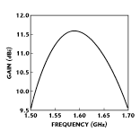
 The gain is measured in the sweep frequency range of 1500 to 1700 MHz so that the antenna performance is checked for a wider bandwidth than the specified frequency band. Figure 6 shows the measured gain vs. frequency plot at boresight direction (q = 0°). The measured antenna gain is 10.6 dBi at 1.525 GHz and 10.9 dBi at 1.661 GHz. These results indicate that the antenna meets the gain specification.
Figure 7 shows the plot of the measured axial ratio vs. scan angle at 1.6 GHz. The plot shows that the axial ratio at boresight direction is 0.8 dB and less than 3 dB within ±20° off the boresight direction. The axial ratio at other frequencies is also measured. The axial ratio is only 0.8 dB at 1.525 GHz and 1.2 dB at 1.661 GHz. A summary of the measured results of the two-element linear array is listed in Table 2 .
|
Table II | ||
|
Frequency (MHz) |
1525 |
1661 |
|
3 dB E-plane beamwidth (º) |
32 |
32 |
|
3 dB H-plane beamwidth (º) |
74 |
74 |
|
Gain (dB) |
10.6 |
10.9 |
|
Axial Ratio (dB) |
0.8 |
1.2 |
The 2 x 2-element Sequentially Fed Array
 The E- and H-plane radiation patterns of the 2 x 2-element sequentially fed antenna array were measured in the anechoic chamber at 1.6 GHz, as shown in Figure 8 . The radiation pattern plots show that the 3 dB beamwidth is 34° for the E-plane pattern and 30° for the H-plane pattern. The side lobes show asymmetry both in the E- and H-planes;
 they are 10 and 13 dB down off the main beam for the H-plane, and 15 and 26 dB for the E-plane. A three-dimensional plot of the antenna's near-field radiation pattern is shown in Figure 9 , displayed in the holographic zone using an xy-scan at a distance of 1 m at 1.6 GHz.
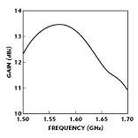
 Having achieved satisfactory radiation patterns, the antenna gain was measured and the results are shown in Figure 10 . Gain is 13.1 dBi at 1.525 GHz and 11.8 dB at 1.661 GHz. This measured performance confirms that the antenna meets the required specification.
In the next step, the on-axis axial ratio vs. frequency of the 2 x 2-element sequentially fed planar antenna was measured and is shown in Figure 11 . The plot shows that the axial ratio is less that 0.45 dB at 1.525 GHz and 1.7 dB at 1.661 GHz. These are very satisfactory results compared to the required specification of 6 dB. The measured results of the 2 x 2-element sequentially fed array antenna are listed in Table 3 .
|
Table III | ||
|
Frequency (GHz) |
1.525 |
1.661 |
|
3 dB E-plane beamwidth (º) |
34 |
34 |
|
3 dB H-plane beamwidth (º) |
30 |
30 |
|
Gain (dB) |
13.1 |
11.8 |
|
Axial Ratio (dB) |
0.45 |
1.7 |
Outdoor Field Trials
Finally, the antennas were tested outdoors while connected to an NEC S1 transceiving terminal8 in the South-East Queensland region of Australia. In all of the investigated cases, the antennas were separated from the briefcase terminal and placed on the case to examine the flexibility of operation. The antenna was pointed toward the satellite with the aid of the map and compass installed in the terminal. The tests were performed under different climatic conditions such as clear sky, cloudy sky and rain.
The received power in all climatic conditions did not vary substantially. The received power levels, as indicated by the phone handset, were in the range of 10 to 11 for the two-element linear array and 12 to 13 for the 2 x 2-element sequentially fed planar array antenna. These instrument readings represent very good signal strength according to the user's manual of the Mobilesat transceiving terminal.8 Note that according to the manual a reading of 04 represents the threshold and a reading of 20 corresponds to overload. Using the experimental setup, a call from the satphone to a PSTN user via Optus B series satellites was also attempted. No matter which of the two antennas was used, a high quality voice link was established.
Antenna Comparison
A summary of the two developed antenna systems is listed in Table 4 . Comparison of the two antennas clearly depicts the superiority of the 2 x 2-element sequentially fed array antenna over the two-element array. The main advantages of the 2 x 2-element antenna are its lower manufacturing cost (A$140), lower weight and superior performance, though the two-element array system has wider beamwidth in the H-plane and, hence, is easier to align with the satellite.
|
Table IV | ||
|
|
Two-element Metallic Disc Linear Array |
2x2 - Element Sequentially Fed Aperture-coupled Patch Array |
|
Total Components |
45 |
33 |
|
Input Connector |
SMA |
SMA |
|
Total Cost (A$) |
170 |
140 |
|
Net Weight (kg) |
2.5 |
0.8 |
|
Dimensions (cm) |
26 x 13 x 1.4 |
26 x 26 x 1.4 |
|
Assembly time (hrs) |
3 mins |
< 1 |
|
Gain (dBi) (min) |
10.6 |
11.8 |
|
Beam Width |
|
|
|
Signal strength (on the Satphone handset monitor) (min) |
10 |
13 |
|
Voice Quality |
very good |
very good/excellent |
Conclusion
Two low cost antenna arrays, a two-element metallic disc linear array antenna and a 2 x 2-element sequentially fed aperture-coupled planar array antenna, have been investigated. The two-element antenna array has demonstrated satisfactory performance in terms of antenna beamwidth, gain and axial ratio. The disadvantages of this antenna include an intensive assembly process due to the large number of components, probe soldering and a relatively large structure (weighing more than 2.5 kg). In contrast, the 2 x 2-element sequentially fed aperture-coupled antenna array appears to be advantageous in terms of its fully planar design, assembly using tiered layers without probe soldering, lower cost due to the use of inexpensive materials and readily available components, and suitability for the portable briefcase terminal since it weighs less than 1 kg. Satphone manufacturers and vendors should develop considerable interest in the antenna system due to these advantageous features.
Acknowledgment
The work described in this article was supported by the Australian Research Council Large Research Grant. The RO3003 PCB material is a product of Rogers Corp., Chandler, AZ. Academy Layout is a product of HP EEsof, Santa Rosa, CA.
References
1. W.W. Wu, E.F. Miller, W.L. Pritchard and R.L. Pickholtz, "Mobile Satellite Communications," Proceedings of IEEE, Vol. 82, No. 9, September 1997, pp. 1431-1448.
2. R. Scrase, "Where Cellphones Daren't," TRANSAT, Inmarsat, London, UK, November 1995, pp. ii - xvi.
3. Eddie Skender, "Choose the Right Mobilesat Antenna," http://members.network.net.au/~transair/msatant.html, Transair, Australia, October 9, 1996.
4. Mobilesat System Description, Optus Communications Technical Documents, Copyright 1992.
5. N.C. Karmakar and M.E. Bialkowski, "On the Modeling of a Cavity Enclosed Broadband Circular Patch Antenna for L-band Land Mobile Satellite Communications," Microwave and Opt. Technical Letters, John Wiley and Sons, December 1995, pp. 784-787.
6. N.C. Karmakar and M.E. Bialkowski, "A 2 x 2-element Sequentially Rotated Patch Antenna Array for a Mobilesat Briefcase Antenna System," Microwave and Opt. Technical Letters, John Wiley and Sons, Vol. 13, No. 1, September 1996, pp. 7-10.
7. M. Haneishi and Y. Suzuki, "Circular Polarization and Bandwidth," Handbook of Microstrip Antennas, Vol. 1, Edited by J. R. James and P.S. Hall, Peter Peregrinus Ltd., London, UK, 1989, pp. 219-274.
8. NEC Satellite Telephone S1 User Manual, Document No. 53-21476-3005, Copyright 1994, NEC Australia.
Nemai C. Karmakar received his BSc and MSc degrees in electrical and electronic engineering from Bangladesh University of Engineering and Technology, Dhaka, Bangladesh, his MSc degree in electrical engineering from the University of Saskatchewan, Canada and his PhD degree from the University of Queensland, Brisbane, Australia, in 1987, 1989, 1991 and 1999, respectively. Currently, he is an assistant professor at Nanyang Technological University, Singapore. Karmakar's research interests cover broadband microstrip antennas and arrays, beamforming networks, near-/far-field antenna measurements, microwave device modeling, and monostatic and bistatic radar. He has published more than 30 technical papers, reports and book chapters, and is a member of the IEEE.
Marek E. Bialkowski received his MEngSc degree in applied mathematics and his PhD degree in electrical engineering from the Warsaw Technical University, Warsaw, Poland, in 1974 and 1979, respectively. During his academic career he has worked at universities in Poland, Ireland, the UK, Canada, Australia and Singapore. Currently, he holds professorships both at the University of Queensland, Australia and Nanyang Technological University, Singapore. Bialkowski's research interests include antenna systems for mobile satellite communications, low profile antennas for reception of satellite broadcast television programs, conventional and quasi-optical power combining techniques, industrial applications of microwaves and computational electromagnetics. He has published more than 200 technical papers and one book. Bialkowski is a senior member of IEEE.
