
An emerging trend in mobile communications is the parallel usage of multiple radio technologies in mobile devices, tablets and other communications modules. In order to support this parallel operation, the devices are equipped with multiple radio transceivers, which are located extremely close to each other. When the different radio technologies operate simultaneously these transceivers interfere with each other resulting in in-device coexistence (IDC) interference. This article describes the IDC interference problem involving LTE (Band 7) and WLAN (2.4 GHz) technology and evaluates the performance of two different mitigation techniques used to reduce the interference effect.
With the increasing demand to have ubiquitous and seamless data connectivity to several wireless networks, modern day devices are designed to support different radio access technologies (RAT). These devices, e.g., mobile phones, tablets and various other communications modules are capable of supporting different cellular as well as non-cellular communications standards at the same time. For instance, a mobile phone might be connected to a wireless local area network (WLAN)1 router for Internet access in parallel to an established long term evolution (LTE)2 call.
Due to the small size of these devices, the transceivers of different radio technologies are located very close to each other. As a result, when these collocated radio transceivers operate concurrently in the same or adjacent frequency bands, it leads to potential interference between their operations known as in-device coexistence interference. IDC interference affects the receiver sensitivity, thereby degrading the quality of the wanted signal or resulting in the loss of data.
This article discusses the challenge of reducing IDC interference while multiple RATs are operating simultaneously. Reducing IDC interference would prevent degradation of the signal quality without disconnecting the interfering radio signal. The article highlights the coexistence scenario between LTE and WLAN, where LTE Band 7 uplink affects the WLAN 2.4 GHz channels, and discusses possible solutions to mitigate IDC interference. First, the cause of IDC interference is described then the different frequency bands where IDC interference occurs are considered, along with the different RATs involved.
Next, the methodology for calculating the desensitization value is discussed, including a description of a possible test setup required to carry out the measurements. After that, it analyzes the use of two different mitigation techniques in order to reduce IDC interference for the different LTE-WLAN use case scenarios and assesses the measurement results. Finally, the article’s contribution is summarized along with some further possible enhancements and future applications of this work.

Figure 1 The close proximity of LTE, Bluetooth, WLAN and GPS radios makes the device vulnerable to coexistence interference.5
IN-DEVICE COEXISTENCE PROBLEM AND SCENARIOS
As the term ‘in-device’ suggests, such interference arises due to the proximity of transceivers of different radio technologies that are situated on the same platform. Consequently, when these different RATs operate simultaneously in the same or adjacent frequency bands, the transmitter of one technology acts as the aggressor/interferer and affects the other technology’s receiver, which behaves as the victim. There are three main causes of this adverse effect:
- Need of multiple radio technologies for ubiquitous connectivity and limited spectrum availability that leads to concurrent operation of these different radio technologies in close frequency range.
- Undesirable emissions such as spurious emissions, out-of-band emissions, spectral harmonics and intermodulation products from the aggressor transmitter3 that fall in the frequency range of the victim receiver.
- Inability of the filters at the transceivers of different RATs to properly filter out the unwanted signal due to the overlapping of transition bands of the different radio technologies.4
Eventually, all these effects add up to increase the noise level of the victim receiver, thus reducing receiver sensitivity and leading to receiver blocking or desensitization. Figure 1 illustrates an example of IDC interference where LTE, global positioning system (GPS), Bluetooth (BT) and WLAN transceivers are situated on the same device. When the LTE transmitter is operating it affects the GPS, BT and WLAN receivers and similarly, the BT and WLAN transmitters affect the LTE receivers due to the proximity of the transceivers and operation in the same or adjacent frequency range.

Figure 2 3GPP frequency bands surround the ISM band used for WLAN and Bluetooth.
The IDC interference scenario has gradually spread in the field of wireless communications and users are inadvertently experiencing such interference while using their communications devices. Some common day-to-day scenarios where the users might experience this interference include usage of LTE and WLAN portable routers, LTE and WLAN offloading, LTE voice over Internet protocol (VoIP) calls, multimedia and other possible applications such as Bluetooth headsets, etc.
As mentioned, one of the main reasons for IDC interference is limited availability of frequency spectrum for simultaneous operation of several RATs. Such a situation can be observed in the 2.4 GHz industrial, scientific and medical (ISM) frequency bands lying in between the 3GPP frequency bands, resulting in adjacent operational frequencies with small or no guard band between various RATs.5
As illustrated in Figure 2, WLAN and Bluetooth technologies operate in the ISM Band, where the lower boundary of this band is adjacent to LTE Band 40 operating in TDD mode and the upper boundary is near the uplink frequency region of LTE band 7 (operating in FDD mode), with a band gap of approximately 20 MHz.5 Since LTE Band 40 is working in TDD mode, the transmitter of LTE Band 40 affects WLAN and Bluetooth receiver operation and similarly, the WLAN and Bluetooth transmitters affect the functionality of the LTE band 40 receiver.
Likewise, the uplink frequency of LTE Band 7 affects WLAN and Bluetooth reception since the Band 7 uplink is situated close to the ISM band. Another coexistence scenario occurs between the navigation satellite system and LTE frequency Bands 13 and 14 as shown in Figure 2, where the receivers of the navigation system are affected by the 2nd harmonics of LTE Bands 13 and 14 uplink frequencies. The uplink frequencies of LTE bands 13 and 14 operate in the range of 777 to 787 MHz and 788 to 798 MHz respectively, and the 2nd harmonics of these LTE Bands fall in the operational frequency range of global navigation satellite system (GNSS) receivers being used for commercial civil purposes,4,5 thereby causing interference.

Figure 3 Packet error rate measurement, with and without interfering signal.
METHODOLOGY AND TEST SETUP
The influence of IDC interference on the operation of different RATs can be analyzed using the desensitization value of the receiver being affected. This desensitization value is based on the receiver’s sensitivity performance, which is measured first in the absence of the interfering signal and then again in the presence of the interfering signal as shown in Figure 3.
It illustrates a packet error rate (PER) measurement scenario where the x-axis represents the power level being received at the receiver in dBm and the y-axis represents the PER value in percentage. As the power level is reduced, the PER value starts increasing, which is shown by the gradual increase in the slope of the curves or the knee of the curves, and the power level at which the PER value reaches 10 percent is defined as the sensitivity of the receiver. Using this receiver’s sensitivity, two different types of receiver power levels or sensitivity terms can be defined – receiver or intermediate sensitivity and effective intermediate sensitivity, which can be used later to determine the desensitization value of the receiver as depicted in Figure 3.
Receiver or intermediate sensitivity is the receiver power level that corresponds to the 10 percent PER value measured in the absence of any interfering signal. Similarly, the power level corresponding to the 10 percent PER value measured in the presence of an interfering signal is known as effective intermediate sensitivity. Finally, the difference between these two receiver sensitivity parameters defines the desensitization value as shown in the following equation:6
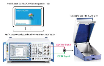
Figure 4 One test setup for performing in-device coexistence interference measurements.
Desensitization Value = Effective Intermediate Sensitivity Level - Intermediate Sensitivity Level
A prototype test setup for IDC interference measurement and analysis can be put together using the test setup shown in Figure 4. Since most radiocommunications in a real-world scenario takes place over the air (OTA), the IDC interference analysis and measurements were carried out OTA. The wideband radio communication tester was used to generate two different radio signals, i.e. WLAN and LTE signals on different RF channels as required and interfering signals. The DUT was placed in an isolated environment, e.g., inside a shield box in order to isolate the device from any external interfering signals.
The two radio signals were combined using a coupler and fed to the antenna coupler board of the RF shield box using RF cables. The radio links established via the communication tester were bidirectional in order to generate the victim and aggressor radio signals and to measure not only the DUT receiver characteristics of the victim technology but also the DUT transmitter quality of the aggressor technology.
The entire setup was controlled using a sequencer software tool, which was installed on a laptop or PC and managed the operations of wideband radio communication tester via SCPI commands. In order to control the DUT placed inside the shield box, a USB connection was established between the DUT and the controller laptop that enabled the software to manage the DUT’s operation using Android Debug Bridge (ADB) commands.
MITIGATION TECHNIQUES AND RESULTS
In order to analyze the IDC interference effect of LTE Band 7 uplink on WLAN, the first and foremost step was to establish a proof of concept. To implement such a concept, most of the RAT parameters were selected in a way so as to simulate a severe interference scenario between the two radio technologies. The following approaches were considered:
- The two RATs, i.e., LTE acting as the aggressor technology and WLAN as the victim technology, were placed as close as possible to each other in the frequency domain.
- The RAT causing interference was configured to transmit at maximum power level.
- Continuous or heavy traffic was generated by the interfering RAT.
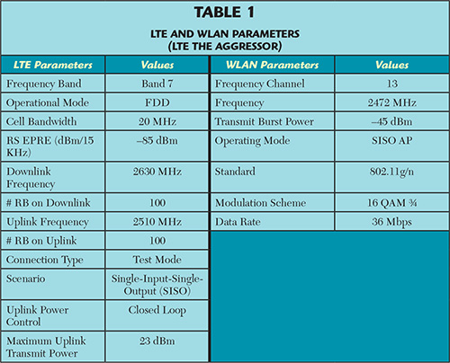
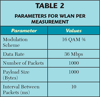
First, the WLAN connection was set up using the parameters in Table 1 and the PER value was measured as a factor to determine the sensitivity performance of the DUT’s WLAN receiver. The details of the parameters used for the PER measurement are in Table 2. The WLAN receiver inside the DUT was able to receive most of the packets efficiently as sent by the WLAN access point (AP), even when the transmit power of the AP was low at around -80 dBm as illustrated by the ‘Only WLAN’ curve in Figure 5.
The LTE connection was then established as per the parameters defined in Table 1, and the WLAN PER measurements were carried out once more in order to study the effect of the interference. When the PER measurements were carried out again in the presence of the LTE signal, the error value showed a sudden increment at a much higher transmit power of the WLAN AP at around -71 dBm, illustrated by the ‘LTE + WLAN Ch 13 (mean)’ curve shown in Figure 5. Finally, the desensitization of the WLAN receiver caused by the IDC interference from LTE band 7 uplink was measured using the difference in sensitivity level of the two PER curves, and calculated as shown in the following equation.
Desensitization Value = Effective Intermediate Sensitivity Level – Intermediate Sensitivity Level
= (-70.64 dBm) – (-79.84 dBm)
= 9.2 dB

Figure 5 WLAN Channel 13 (fC = 2472 MHz) desensitization by LTE Band 7 uplink (fC = 2510 MHz), with an uplink transmit power of 23 dBm.
Once the IDC interference effect between LTE and WLAN was detected, the next step was to analyze the various possible mitigation techniques that might help in reducing the interference effect. One way to avoid IDC interference is to increase the band gap between the aggressor technology and the victim radio technology. 4,5,7 In other words, the victim radio technology is moved away from the interfering radio technology or vice-versa, to another frequency range that lies a certain band gap away. Due to an increment in the band gap between the two radio technologies, the transition bands of these technologies do not overlap even if these two RATs are operating at the same time.
As a result, the RF filters are able to properly distinguish between the wanted and unwanted signals, thereby reducing the impact of IDC interference. Figure 6 illustrates this mitigation technique, where the various colored curves represent the different frequency channels of WLAN operating simultaneously with the LTE Band 7 uplink signal. As the WLAN frequency channel is gradually shifted away from the LTE uplink carrier frequency, the band gap increases between the LTE and WLAN signals, leading to a comparatively reduced interference effect.
IDC interference can also be suppressed by reducing the signal strength of the interfering signal. Unwanted transmitter emissions such as out-of-band emissions, intermodulation products and spurious emissions are directly related to the transmit power, i.e. the higher the transmit power, the higher the magnitude of these emissions, resulting in more interference. Furthermore as mentioned earlier, these unwanted emissions from the interfering RAT reduce the sensitivity of the victim RAT’s receiver, leading to suppression of the wanted signals or loss of data at the receiver end. In order to reduce the effect of IDC interference, one possible solution is to reduce the transmit power of the aggressor technology.
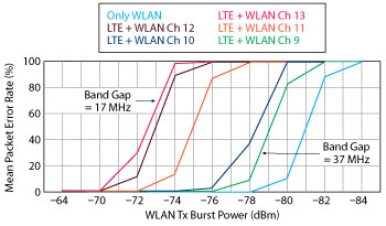
Figure 6 WLAN frequency shifting with the LTE Band 7 uplink (fC = 2510 MHz with 23 dBm transmit power) acting as the aggressor.
Figure 7 represents an IDC interference scenario where LTE Band 7 uplink acts as the main source of interference for the WLAN receiver. The IDC interference effect can be reduced by decreasing the LTE uplink power, eventually reducing unwanted emissions. The various colored curves in Figure 7 depict the different power levels of the LTE Band 7 uplink signal operating concurrently with WLAN receiver operations. As the LTE uplink power level is reduced, the unwanted emissions from the LTE end also decrease, resulting in comparatively less interference.
In addition to the mitigation techniques mentioned above, there are a few more approaches that might reduce the IDC interference effect. One possible technique is to distribute or schedule the operational time between LTE and WLAN in such a way that the transmission time of one technology does not coincide with the reception time of another technology. In this way, even if these two technologies were operating in the same or adjacent frequency bands, they would not interfere with each other.4,5,7 Another method is to shift the resource blocks (RB) allocated to the UE for LTE uplink data transmission to a frequency range away from the WLAN technology. In other words, the RBs that are situated far away from the operational frequency of WLAN are used for data transmission on the LTE uplink and downlink. This increases the band gap between LTE and WLAN, thereby improving the filtering performance of the RF filters.
The aforementioned techniques offer a promising effect in mitigating IDC interference between LTE and WLAN, yet these mitigation techniques have their own limitations. The selection of a particular mitigation technique depends upon the combinations of the RATs, which defines the RAT acting as the aggressor or interferer technology and the RAT acting as the victim technology. It also depends on the ease of implementation of these techniques considering the state-of-the-art features of the two technologies. Techniques such as reducing the transmit power reduces the interference effect by reducing the LTE uplink power level. However, the LTE uplink power is high only when the channel quality is bad, for example the UE might be inside a tunnel, in the basement of a building or at the cell edge.

Figure 7 LTE transmit power control with LTE Band 7 uplink (fC = 2510 MHz) acting as the aggressor for WLAN Channel 13 (fC = 2472 MHz).
Subsequently, reducing the uplink transmit power in order to reduce the IDC interference effect might actually result in the LTE call being dropped or a reduction in data throughput. The frequency shifting technique reduces the interference effect by increasing the band gap between the two radio technologies. However, the biggest challenge lies in the availability of frequency spectrum as there might be a scenario where no frequency range is free or where all the frequency channels are experiencing interference from another radio technology. Similarly, modifying the relative position of RB in the allocation grid or scheduling the operational time of different RATs could also be used to reduce the interference effect.
However, the implementation of these techniques would depend upon the availability of the subcarriers for shifting the RB and on data throughput plus the delay restrictions while scheduling the operational time.
CONCLUSION
The growing number of wireless devices equipped with multiple RAT transceivers is being driven by the increasing user demand and the stringent requirements of new applications and services that necessitate the operation of several RATs in parallel. Simultaneous operation of these collocated RAT transceivers in the same or adjacent frequency bands results in IDC interference and loss of useful data. This article discussed different techniques that might help mitigate this interference effect. However, these techniques have some drawbacks and are still being discussed in 3GPP before being implemented in the LTE protocol layers.
Analysis of IDC interference and possible solutions to mitigate such interference would be quite instrumental in manufacturing wireless chipsets and devices, the innovative Internet of Things (IoT) scenario – especially machine-to-machine (M2M) communications, the automotive industry and futuristic communications technologies that would involve using multiple RATs in the same communications channel.
Note:
- The IDC measurement results shown in this article are device-specific and may vary from one device to another.
- All the measurements were executed five times in order to obtain an average value.
- The PER measurements were carried out with a receiver power step size of 2 dB, thereby resulting in sharp edges of the PER measurement curves. A higher granularity of power steps would have resulted in a longer measurement time.
References
- IEEE Standards Association, “IEEE 802.11TM: Wireless LANs,” October 2015, www.standards.ieee.org/about/get/ 802/802.11.html.
- 3GPP A Global Initiative, “LTE Technology Overview,” October 2015, www.3gpp.org/technologies/keywords-acronyms/98-lte.
- ITU-R Radiocommunication Sector of ITU, “Unwanted Emissions in the Spurious Domain,” Recommendation ITU-R SM.329-12, 09/2012.
- Zhenping Hu, R. Susitaival, Zhuo Chen, I-Kang Fu, P. Dayal and S.K. Baghel, “Interference Avoidance for In-device Coexistence in 3GPP LTE-Advanced: Challenges and Solutions,” IEEE Communications Magazine, Vol. 50, Issue 11, pp. 60–67, November 2012.
- 3GPP, Technical Specification Group Radio Access Network, Evolved Universal Terrestrial Radio Access Network (E-UTRA), “Signaling and Procedure for Interference Avoidance for In-device Coexistence,” Release 11, 3GPP TR 36.816 v11.2.0 (2011-12).
- Detlev Liebl and Bernard Schulz, “LTE and Bluetooth In-device Coexistence with WLAN,” Application Note, 1MA255, Rohde & Schwarz, 2015.
- S.K. Baghel, M.A. Ingale and G. Goyal, “Coexistence Possibilities of LTE with ISM Technologies and GNSS,” National Conference on Communications 2011 (NCC), pp. 1–5.
- Abinash Sinha, Prof. Dr. Wolfgang Kellerer, Reiner Stuhlfauth, Fernando Schmitt, and Thomas Feddersen, “Master’s Thesis: Analysis of In-Device Coexistence Interference,” Rohde & Schwarz and Technische Universität München, October 2015.