140 GHz Extender Modules for Vector Network Analyzers
Anritsu Co., Microwave Measurements Division
Morgan Hill, CA
For nearly the entire history of microwave communications, the characteristics of the mm-wave spectrum between 100 and 140 GHz have intrigued scientists and designers alike. The future of this formerly remote portion of the spectrum has never looked brighter as commercial communications service providers eye its potential to produce revenue and the defense industry exploits its unique characteristics.
With this increased interest comes a need to test the mm-wave components that will compose the mid-100 GHz systems. To accommodate this requirement, two frequency extension modules have been introduced for the Lightning series vector network analyzers (VNA) that extend the instruments' measurement range to 140 GHz (F band). The model 3740A-F extender module performs both transmission and reflection measurements (two are needed for two-port measurements); the model 3741A-F enables transmission measurements only and must be used with a 3740A-F module to make one-port measurements. Like all of the mm-wave measurement modules available for the Lightning series VNAs, these devices combine the frequency conversion, mixing and signal routing circuits required to make mm-wave S-parameter measurements. Signal connection is via WR-8 waveguide.
High Output Power
 One of the problems confounding S-parameter measurements at very high frequencies is the difficulty in obtaining adequate output power. The models 3740A-F and 3741A-F modules are designed with more than adequate power across their operating frequency range, as shown in Figure 1 . Receiver dynamic range (the ratio of maximum signal at port 2 at 0.1 dB gain compression to system noise floor (specified at -93 dBm)) is 98 dB. System dynamic range typically is greater than 90 dB for the complete test system, as shown in Figure 2 .
Operation
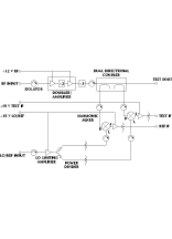
A synthesizer in the Lightning series VNAs is used as the RF source and is  programmed to deliver its output at one-sixth the desired measurement frequency. Figure 3 shows the F-band extender modules' architecture, which is the same as their predecessors for Q, V, E and W bands. Table 1 lists the extender modules' typical performance specifications. The RF signal enters the mm-wave module, is doubled and amplified, and then tripled. This signal then travels to the test port where the first harmonic mixer generates a reference IF signal. A dual-directional coupler samples the RF signal reflected or transmitted from the device under test (DUT). This signal provides the RF input to the second harmonic mixer, which, in turn, is used to generate the test IF signal.
|
Table I | |
|
Frequency Range (GHz) |
90 to 140 |
|
Maximum signal into port 2 (dBm) |
+5 |
|
Noise Floor (dBm) |
-93 |
|
Receiver dynamic range (dB) |
98 |
|
System dynamic range (dB) |
90 |
|
High level noise (dB) |
0.1 |
|
Power delivered to DUT (dBm) |
-3 |
|
Directivity (dB) |
> 42 |
|
Source match (dB) |
>32 |
The synthesizer used as the LO source is programmed to a 270 MHz offset from the desired DUT frequency. After entering the mm-wave module, the LO signal enters a limiting amplifier that maintains the LO power at a fixed level for injection into the harmonic mixers. The LO signal is split to provide inputs for the harmonic mixers, which use the LO signal's eighth harmonic.
In the first harmonic mixer, the eighth harmonic of the LO is mixed with the sampled RF signal from the DUT to create a 270 MHz reference IF signal to input to the VNA. In the second harmonic mixer, the eighth harmonic of the LO is mixed with the RF signal reflected or transmitted from the DUT, creating the 270 MHz test IF, which is input to the VNA.
Conclusion
While the mid-mm-wave spectrum is currently sparsely populated, commercial communications applications as well as scientific applications (such as radio astronomy, remote sensing and mapping) and military uses (such as battlefield radars and communications systems) point the way toward greater use of this segment of the mm-wave spectrum. For designers working in these and other fields, the models 3740A-F and 3741A-F extender modules are welcome replacements for the laboratory-assembled measurement solutions employed currently.
The models 3740A-F and 3741A-F extender modules are available for delivery in 26 weeks. They are priced at $78 K and $38 K, respectively.
Anritsu Co., Microwave Measurements Division, Morgan Hill, CA (408) 778-2000.
Circle No. 301
