A Conductor-loaded Resonator Filter with a Wide Spurious-free Stop Band
K&L Microwave Inc.
Salisbury, MD
The newly opened personal communications service (PCS) market demands a large number of base station filters with extraordinarily strict requirements on both in-band and out-of-band characteristics. High selectivity, high rejection, low loss and extremely wide spurious-free performance are required for both transmitter and receiver channels. Furthermore, the filters must have small size and low cost to be accepted by the market.
The strict requirements on the filter make it difficult to realize. Resonators with high unloaded Qs and an elliptic function response filter must be used to satisfy the loss and high rejection requirements.1 Resonators with good spurious-free performance are needed to meet the out-of-band requirements. Although dielectric-loaded resonators have higher unloaded Qs, they have spurious responses that are too close to the desired passband.2,3 To satisfy the out-of-band requirements using a dielectric-loaded resonator filter, a lowpass filter with a high rejection response is required in conjunction with the dielectric-loaded filter. Thus, the size, loss, cost and complexity of the filter assembly increase significantly. Coaxial and combline filters have good spurious performance but not very high unloaded Qs,4,5 and cannot satisfy the loss requirement of the systems. The conductor-loaded resonator filter, which has both high unloaded Qs and relatively good spurious performance, is the desired filter type for this application.6
A new configuration of a conductor-loaded resonator filter has been developed. By using two different-sized conductor-loaded resonators, the resonant frequencies of the spurious modes of two coupled resonators are shifted apart. Thus, the spurious response close to the filter’s center frequency is suppressed completely. A rigorous mode-matching method was used to compute the resonant frequency, unloaded Q and fields of the desired resonant mode, as well as the spurious higher order modes of the conductor (solid or ring)-loaded resonators. The coupling coefficients between two resonators were computed efficiently using small aperture theory. The mode charts and the unloaded Qs of the resonators are presented and an eight-pole elliptic function filter is designed and constructed.
Configuration and Analysis
The configuration of an eight-pole, dual-mode, elliptic function, conductor-loaded resonator filter is shown in Figure 1 .  Different-sized conductor-loaded resonators operating in the HE11 mode differentiate the resonant frequencies of the resonators’ spurious modes. Because the spurious modes have different resonant frequencies, the filter’s spurious response near the center frequency is suppressed significantly. Thus, the filter achieves better spurious performance.
To design the proposed filter successfully, the dimensions of the resonators must be determined accurately by computer simulation. The conductor-loaded resonators’ configurations for solid and ring types are shown in Figure 2 .  A rigorous mode-matching method is used to compute the resonant frequency, unloaded Q and resonant-mode fields. In this method, the resonators are divided into several regions in the radial direction where the solid resonator can be considered a special case of the ring resonator. The mode fields in each region are expressed as the summations of their own waveguide eigen modes. Then, the tangential electric and magnetic fields are forced to be continuous at the interfaces between regions I and II and between regions II and III if the resonator is the ring case. By using the proper inner products, a characteristic matrix for resonant frequency can be obtained. The resonant frequency and the field coefficients of the resonant mode can be obtained by determining the frequency that produces the zero determinant of the matrix.
Experimental Results
An eight-pole, elliptic function filter with a center frequency of 1.8575 GHz and bandwidth of 15.5 MHz for PCS base station applications was designed, constructed and tested.  The input/output resistances and the coupling matrix elements of the filter are R1 = R2 = 1.2101 ohm, M12 = M78 = 0.8153, M23 = M67 = 0.8465, M34 = M56 = 0.4292, M45 = 0.5408, M14 = M58 = –0.4119 and M36 = –0.0109. Based on previous analysis and computer simulation, the dimensions of the cavities are determined. Solid conductors are loaded into the cavities of different radii.
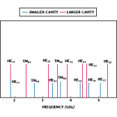
  The unloaded Qs of the cavities are 9500 and 12,000, and both the inner conductor and enclosure are silver plated. Figure 3 shows the spectrum of the two resonators. It is expected that the TM01, HE21 and TM02 modes of the resonators can be suppressed significantly. Figure 4 shows the measured frequency responses of the test filter. The filter’s insertion loss at the center frequency is 0.72 dB. The corresponding realized unloaded Q of the filter is greater than 6000.
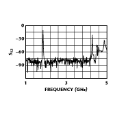
  Figure 5 shows the wideband frequency response of the eight-pole filter. The spurious-free performance of the filter extends to 4.2 GHz or 2.26 f0. The spurious performance of the filter is much better than that of the HE11-mode dielectric-loaded filter of 1.2 f0, the TE01-mode dielectric-loaded filter of 1.5 f0 and the same-sized conductor-loaded resonator filter of 1.9 f0.
Conclusion
A new dual-mode filter configuration using different-sized conductor-loaded resonators has been presented. By differentiating the resonant frequencies of the two resonators, the spurious level of the nearby modes is suppressed significantly. A rigorous mode-matching technique was used to compute the resonant frequency, unloaded Q and resonator fields. The coupling coefficients between the two resonators were obtained by small aperture approximation. An eight-pole test filter was designed, constructed and tested, and the measured results verify the theory.
Acknowledgment
A partnership was entered into between K&L Microwave, the University of Maryland and the state of Maryland under the Maryland Industrial Partnership Program (MIPs). MIPs is intended to generate new jobs for Maryland residents while the company receives top-quality research and development without dedicating vast internal engineering resources. The development of the filter described in this article is a direct result of that partnership and demonstrates the merits of the MIPs program. Other individuals who assisted with product development include Chi Wang and Kawthar A. Zaki, chief engineers at the University of Maryland, Ali E. Atia, president of CTA Inc. and Tim Dolan, vice president of engineering at K&L Microwave.
References
1. A.E. Atia and A.E. Williams, “Narrow Bandpass Waveguide Filters,” IEEE Transactions on Microwave Theory and Techniques , Vol. MTT-20, April 1972, pp. 258–265.
2. S.J. Fiedziuszko, “Dual-mode Dielectric Resonator-loaded Cavity Filter,” IEEE Transactions on Microwave Theory and Techniques , Vol. MTT-30, September 1982, pp. 1311–1316.
3. S.J. Fiedziuszko, “Practical Aspects and Limitations of Dual-mode Dielectric Resonator Filters,” 1984 IEEE International Microwave Theory Symposium Digest , 1985, pp. 353–356.
4. G.L. Matthaei, “Combline Bandpass Filters of Narrow or Moderate Bandwidth,” Microwave Journal , Vol. 6, August 1963, pp. 82–91.
5. Hui-Wen Yao, Kawthar A. Zaki, Ali E. Atia and Rafi Hershtig, “Full-wave Modeling of Conducting Posts in Rectangular Waveguides and Its Applications to Slot-coupled Combline Filters,” IEEE Transactions on Microwave Theory and Techniques , Vol. MTT, December 1995, pp. 2824–2830.
6. K.A. Zaki, C. Wang and A.E. Atia, “Dual-mode Conductor-loaded Cavity Filters,” 26th European Microwave Conference , 1996, pp. 159–162.
K&L Microwave Inc., Salisbury, MD (410) 749-2424.
