A Miniature Patch Antenna for GPS Applications
Toko America Inc.
Mt. Prospect, IL
With the number of Global Positioning System (GPS)-related consumer products on the rise, the market is demanding low cost, high functionality components for system designs. The DAK series dielectric patch antenna is a low cost antenna element designed to be part of a module for automotive navigation and mayday systems, as well as for use in hand-held GPS units. The DAK unit is a flat dielectric ceramic patch antenna incorporating a rectangular microstrip configuration that is used to receive GPS clear/acquisition code (C/A) right-hand circular polarization waves transmitted by the 24 orbiting Navigational Satellite Timing and Ranging (NAVSTAR) satellites.
Compared to traditional Teflon™-type antenna elements, the DAK antenna is one-quarter the size while maintaining equivalent reception sensitivity. The antenna’s good stability and sensitivity are a result of using high performance proprietary ceramic materials well suited for operation at GPS frequencies. The ceramic material used in the construction has a 20 ppm/°C maximum temperature coefficient, which provides good temperature stability for operation in harsh weather. The silver-plated electrode and slightly off-center feed pin allow for good high frequency characteristics and provide good directivity.
The model DAK1575MS50 antenna element is a flat-patch construction that measures 25 mm sq. by 4 mm thick. Figure 1 shows the antenna’s outline.  The antenna feed is via an offset pin through the ground plane attached to the silver-plated copper patch-type electrode. The antenna is designed for 1575 MHz right-hand circular polarized reception with a 50 ohm impedance.
Because the antenna gain depends on the ground plane size, the larger the ground plane the higher the gain will be to a maximum at 70 mm sq. A ground plane of 50 mm sq. is recommended to obtain sufficient antenna gain. Below 50 mm sq. the antenna’s gain will be reduced. The radiation electrode is designed to provide an ideal impedance match using a square-shaped ground area. The ground plane may be folded up the side of the radome to minimize the antenna’s overall physical layout.
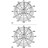
The antenna’s characteristics vary considerably depending on the overall structure of the antenna such as the ground plane shape and dimensions, radome and installation site.  When the antenna is covered with a radome the center frequency shifts down by approximately 5 MHz. For this reason, the antenna electrode is designed for a center frequency of 1580.5 MHz when mounted on an uncovered 70 mm sq. ground plane. Figure 2 shows the antenna’s directivity at 0° and 90°. The gain at zenith and at 10° elevation is +5 dBi (typ) and –1 dBi (typ), respectively.
  Figure 3 shows the antenna’s frequency response, which indicates a minimum 3 dB bandwidth of 9 MHz.
A common method of mounting the antenna is by using double-sided tape to adhere to the ground plane inside the radome. Although the tape acts as an insulator, in this high frequency application a sufficient capacitive coupling exists to provide adequate grounding. Generally, this mounting method shifts the frequency down by another 1.1 MHz. Taking into account this frequency shift and the shift due to the radome cover, the resulting center frequency is approximately 1575.4 MHz.
The DAK miniature patch antenna is helping to make today’s GPS-based systems and equipment smaller, lighter and less expensive. Price: $5.27 each (1000). More information on the antenna can be obtained from the company’s Web site at http://www.tokoam.com.
Toko America Inc., Mt. Prospect, IL (847) 297-0070.
